The Art and Science of GC Capillary Column Production
LCGC North America
In this month's issue, columnist Ron Majors and coauthors discuss the important steps in the successful production of fused-silica gas chromatography (GC) capillary columns.
Compared with the developments in the latter part of the 20th century, today, gas chromatography (GC) is considered to be a mature science with few major innovations occurring. Despite its maturity, there are more gas chromatographs in use today than any other analytical instrument. High performance liquid chromatography (HPLC), despite its higher dollar instrument sales volume, still lags behind GC in the number of installed instruments. When combined with the sales of columns, gases, and accessories, GC represents over a billion dollar a year industry. Even with all of the capital spent on GC products, the column still represents the most important part of the system.

Ronald E. Majors
It often has been stated (or perhaps overstated) that the column is the heart of the chromatograph. Last year, an article on LC columns traced the development of the LC column from the beginning to the present (1). In GC, the "heart" statement holds equally true. From the very beginning, when packed tubes were the only available column technology, appropriate selection of the column hardware and its associated stationary phase were just as important as today in performing successful separations of volatile chemical compounds.
It generally is agreed upon that a major shift in the widespread application of practical GC came about in 1979 with the development of the fused-silica capillary column (2). Before this groundbreaking achievement, GC was practiced using low efficiency packed columns, fragile borosilicate glass capillary columns, and active metal capillary columns. In this installment of "Column Watch," we would like to provide a brief overview of GC columns but quickly shift to the fused-silica capillary column. Here, we will discuss how a fused-silica capillary GC column is constructed in a production setting so that one can appreciate the science, the work and the care that goes into producing that separation device that most gas chromatographers take for granted.
Background in GC Column Technology
Figure 1 classifies GC into the various techniques that are in popular use. Packed-column GC is still in use but has fallen to less than 20% of the column market. It is mainly used for classical hydrocarbon separations, regulated environmental methods and for preparative applications where the sample capacity of capillary columns is too low to provide adequate yields. In gas–solid chromatography (GSC), one uses a solid support such as silica, alumina or other active granular support material to perform gas-phase separation based upon adsorption. For gas–liquid chromatography (GLC), the support, usually a high surface area inert substrate such as Celite, Chromosorb W, or firebrick, is coated with a nonvolatile polymeric liquid stationary phase, usually 3–10% by weight. Analytes partition themselves into this phase depending upon the relative solubilities of the analytes and are separated by virtue of their boiling points and other chemical or physical parameters. GLC is the most popular form of packed-column chromatography. Packed columns generally have internal diameters of 2–4 mm and lengths of 1.5–10 m.
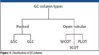
Figure 1
Open-tubular columns are, by far, the most popular GC columns (Figure 2). In open-tubular GC, ideally, a long inert tube is used as the column material. As the name implies, the center of the tube is open so that the carrier gas can freely flow without the resistance of a packing material. In the majority of modern columns, the stationary phase is coated and chemically bonded onto the inner walls of the tube and cross-linked throughout the polymer matrix. There are still a few "classic" columns available where the stationary phase is not bonded but simply coated with a viscous liquid that is considered immobile based upon the stationary phase's relatively low vapor pressure. The nonbonded phases place many analytical restrictions on the chromatographer including low upper temperature limits, high stationary phase bleed and phase washout from solvent injections. In general, the coated phases also have a higher activity towards active solutes that can be present in the sample. The ability of manufacturers to bond and crosslink the stationary phase is certainly one of the key discoveries that made capillary columns a viable and rugged tool in GC. Most any analytical separation that currently uses capillary column with a non-bonded, non-cross-linked phase can be improved by using the equivalent bonded, cross-linked phase (3).
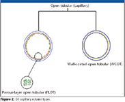
Figure 2
Capillary columns generally have an internal diameter of a few tenths of a millimeter and lengths of 10–60 m. They are constructed of stainless steel, borosilicate glass and, as stated previously, fused silica. Just as in packed column GC, there are different types of capillary columns. Wall-coated open tubular (WCOT) capillary columns have a thin layer of nonvolatile stationary phase coated or bonded onto the inner walls. The thickness of the phase is usually in the range of 0.1–3.0 μm, although thicker films are available. Just as in GLC, analytes partition into this stationary layer and are separated. Because they have an open, mean-flow path and relatively thin stationary phase layers, analytes partition into and out of the stationary phase very quickly and, hence, WCOT capillaries are more efficient than packed GLC columns. Support-coated open tubular (SCOT) capillary columns have their inner walls lined with a thin layer of support material such as diatomaceous earth onto which a stationary phase has been adsorbed. The SCOT columns are generally less efficient than WCOT columns. Finally, porous-layer open tubular (PLOT) capillary columns, which are more accurately called adsorbent layer open tubular (ALOT) capillary columns (4), have a thin layer of porous support material on the inner walls. Depending upon the support materials, layers are generally in the range of 5–50 μm. This form of capillary chromatography is analogous to packed GSC columns where silica or alumina sorbents are adhered to the walls. Packed capillary columns also are available but find limited use.
An intermediate type of column, the micropacked column, a short, narrow stainless steel columns packed with diatomaceous earth solid support, porous polymer, molecular sieve, or other particles. They are generally 1–2 m long with 0.75–1.0 mm internal diameters. As one might suspect, the performance characteristics of micropacked columns are intermediate between those of packed columns and those of capillary columns.
Since WCOT capillaries are the most popular type of GC column and the main steps in their production is similar to some of the other capillary columns, we will focus on this type of column throughout the rest of this installment of "Column Watch."
Steps in the Production of a Fused-Silica Capillary Column
The production of a fused-silica WCOT capillary column is a long and thorough process. As many as 12 individual steps and scores of process checks and validations are performed along the way. At any point, failure to control the process can result in an unacceptable column resulting in this column being discarded and the time and materials wasted. For a standard column (30-m length, 0.25-mm internal diameter and 0.25-μm film thickness) of just about any stationary phase, the average production time is roughly 10 days. When thousands of columns a month are produced, it is imperative that the failure rate be very low. Otherwise, production schedules will be in jeopardy and customers will have to wait to get their columns, especially custom orders.
Table I outlines the steps in the production of a fused-silica capillary column. With the exception of steps 12 and 13, one cannot skip or shorten any of these steps if a consistent column and yield is expected. Steps 12 and 13 include "enhancements" to a capillary column that would make a standard column such as a 50% diphenyl–50% dimethylpolysiloxane phase better suited for performing pesticide analysis rather than using a similar column without the "special" treatments. Without divulging proprietary information, we would like to discuss the individual steps and the parameters that must be controlled to produce an acceptable column at the end.

Table I: Steps in the production of a GC capillary column
Work Order and Production Planning
Table II demonstrates the magnitude of the planning that is required to successfully produce GC columns on a large scale. Shown are different column and cage dimensions that are offered for just one GC stationary phase type (100% dimethylpolysiloxane). The matrix of Table II shows all different combinations, each of which represents a unique part number, that can be ordered for this one phase. Part numbers quickly proliferate when 20–30 different stationary phases are offered in various column and cage dimensions.

Table II: Typical multiple combinations of GC capillary columns for a single stationary phase (100% polydimethylsiloxane)
With over 1000 part numbers in a typical GC column catalog consisting of various column and cage dimensions, film thicknesses and stationary phases and an average of 10 days of production time per column, proper planning is a prerequisite to making the correct number and type of columns to meet user needs. Producing too many of the wrong column slows overall production, allows inventory buildup which is costly and takes up shelf space and can cause a shortage of a more popular configuration that means shipment delays. Producing too few of a popular column also can cause unhappy customers who will be waiting on delivery. Fortunately, historically capillary column usage has been fairly consistent. Figure 3 provides an example of the popularity of the various stationary phases determined in a 2003 survey (5). The workhorse columns are still the more robust and rugged nonpolar stationary phases such as the 100% dimethylpolysiloxane and 5% diphenyldimethylpolysiloxane. Thus, manufacturing the proper number of columns to ensure that the most popular ones are readily available is a primary requisite to user satisfaction.
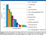
Figure 3
Since each column is manufactured with certain dimensions, stationary phase, film thickness and so on, it is imperative that an individual column be closely monitored through the production process. Bar coding or other portable means of identification is a requirement and a process test or data sheet needs to follow all production steps. Today, individual bar codes are scanned and entered into a computerized database.
Fused-Silica Tubing
The initial step in the production of a GC capillary column is the selection of the fused-silica tubing. Few GC column manufacturers draw their own tubing; most purchase tubing from one or more manufacturers. Most of the fused silica in the world is manufactured for the use in the fiber optics for telecommunications where a continuous solid fused-silica rod is required but GC capillary needs an open hole that is extremely consistent. The extremely small percentage of fused-silica usage for GC capillaries in the world production of fused-silica tubing has caused some problems in calling attention to the demanding requirements of GC. The story behind the technology of fused-silica capillary needs and methods of production for capillary GC was eloquently told in an LCGC article several years ago by Steve Griffin and will not be repeated here (6). It suffices to say that the fused-silica composition, surface contamination, residual glass stress, consistency of inner and outer diameter dimensions, tubing shape (ovalty), the consistency of polyimide coating, and surface activity are all important parameters that must be controlled since one or more of these will influence the successful production of a GC capillary column.
Since two of the most important parameters in terms of the user requirement are the inner diameter and length, it is important to precisely know these dimensions. In addition, the inner diameter is the basis for phase ratio (β) that governs retention (k). Knowledge of the tolerance of tubing inner diameter is imperative and must be measured rather than accepting the nominal value. Tubing inner diameter tolerance must be specified since the number is required for the exact flow rate setting for automated electronic pressure control in the gas chromatograph. All manufactured columns, the actual inner diameter should be provided on the column test sheet.
Capillary Tubing Winding
The first step in column production is winding the bare fused-silica capillary onto the proper cage size. The column cage is the device usually constructed of stainless steel that actually mounts inside of the GC oven. It must be sturdy and hold the capillary in a fixed position even with vibrations within the oven caused by the fan. In addition, the cage should not add unwanted heat capacity variances inside of the oven that could cause poor reproducibility of the heating and cooling profile or to the column tubing itself. Different GC oven sizes and brands require different sizes of column cages.
It would be extremely inconvenient to manufacture columns while in a straightened configuration. Thus, all the steps in column production are performed with the fused-silica capillary wound onto a column cage.
For modern column production, the winding process is automated and, thus, the tubing length can be controlled precisely. Tubing length, of course, is the other important dimension parameter in achieving retention time reproducibility. So, consequently, the column must be cut to the actual length at the end of the production cycle. It is important that the analyst keep track of the length reductions when trimming the column as part of routine maintenance procedures.
Tubing Preparation and Deactivation
Compared to borosilicate glass capillaries of yesteryear, fused-silica tubing is considered to be rather inert. Since the composition of this tubing is still SiO2-based, surfaces do possess some residual activity that can be from trace impurities (for example, metals) or, in particular, free silanol (Si-OH) groups that are ubiquitous on all untreated silica-based materials. One of the most important steps in column production is to ensure that the fused-silica tubing surface is consistent from column-to-column and batch-to-batch. Before coating a stationary phase, the fused-silica surface must be prepared so that its impact on the final column performance is minimized. If the underlying surface is different from previous treatments, then the stationary phase might not adhere properly and the influence of surface silanols or tubing impurities can manifest themselves for polar, basic, or acidic analytes that can be chromatographed during subsequent usage. It is now generally agreed upon that the choice of surface treatment and, in particular, the type of deactivation that is applied sedulously before coating the stationary phase onto the surface has a profound effect on the stationary phase bleed and to some degree on column stability.
Various GC column manufacturers consider many of these surface treatments highly proprietary but it suffices to say that the deactivation step is extremely important in the final outcome of a column's performance with demanding samples. The nature of this deactivation "layer" is where columns with the same stationary phase but from different manufacturers actually might differ in their performance. Normally, one would surmise that a column with the stationary phase of 5% phenyl–95% dimethylpolysiloxane from one manufacturer would not be unlike the same polymeric coating from another manufacturer. After all, they are coated with the same polymer. This observation might be true for 90+% of the applications, especially for neutral compounds like hydrocarbons. However, for polar compounds, especially those with acidic (for example, phenols and carboxylic acids) or basic (for example, amines) functional groups, the underlying silanols or other surface impurities can cause irreversible adsorption, strong tailing or other undesirable features. The inertness of the columns might be different due to the deactivation process.
A first step to ensure consistency of the fused silica is a leaching step. Referring to the paper of Griffin (6), fused-silica tubing can have such impurities as chlorine, acids of nitrogen and other sources of catalytic activity. These must be removed or they can later come back to haunt the user during the application of the column. A deactivation program for fused-silica capillaries suitable for most applications entails an acid wash (5). In such a treatment, traces of heavy metal ions that can cause adsorption effects can be removed. In addition, just like in HPLC silica particles, surface silanols are always present on the fused-silica surface and must be deactivated sufficiently. Thus, by appropriate chemical treatment, the fused-silica surface is hydrolyzed fully so that the concentration of silanols is maximized but also normalized from batch-to-batch.
Then, the next step in the process is to deactivate (block) these silanols. The deactivating reagents can vary from company-to-company and phase-to-phase but their purity must be controlled and evaluated prior to use. Otherwise, the reagent itself can cause variations in the deactivation layer. So both its purity and composition must be independently checked before use. Usually, the type of reagents used can be organochlorosilanes, alkoxysilanes, hexamethyldisilazine, or other reactive compounds. The reaction conditions must be controlled; so this deactivation is performed in a temperature-controlled environment. Finally, before the coating step in the manufacturing process, there might be additional deactivation steps employed to ensure that the surface is ready to accept a nonpolar or a polar stationary phase. Thus, its "wettability" for the stationary phase at hand must be assured. With this treatment, the stationary phase film will spread evenly. An uneven film will adversely affect column efficiency. Before coating, the final step is usually a wash with a pure solvent followed by drying in an inert atmosphere.
Stationary Phase Coating
Once the column has been sufficiently treated to ensure inertness, it is ready for the coating step. Obviously, the coating step is of utmost importance since the stationary phase determines the chromatographic resolution and reproducibility. The phase should be uniform in thickness and be homogeneous throughout the column and it should adhere tightly to the inner walls so that there is no disruption during programmed temperature cycles or during injection of solvent and sample. Modern phases usually are immobilized by cross-linking, which gives them added stability over coated phases. Such phases can be solvent-washed if contaminated.
The type of stationary phase is dictated by the application. Popular stationary phases are shown in Figure 3. Most stationary phases are polymeric in nature. It is important for the manufacturer to maintain control over the polymeric materials used to coat the column. Rather than relying on an outside vendor to provide a polymer for use in the preparation of GC capillary WCOT columns, some manufacturers will prepare their own polymers for use as GC stationary phases. They will synthesize the polymer, purify it, and pretest the purified polymer before actually using the polymer for GC column coating. In this manner, they can be assured that the polymer that they use for column preparation six months or two years from now will match the polymer that was used for today's column coating. For copolymers, it is important to control the substitution percentage (for example, 50% diphenyl–50% dimethylpolysiloxane). Otherwise, if the composition is only 48% diphenyl on today's batch and 52% on next year's batch, it will not have reproducible retention characteristics. A check of retention indices for selected test probes will ensure that the composition is accurate. It is especially important to remove lower molecular weight fractions since these fractions can cause column bleed, especially at high temperature. So, column bleed is checked before accepting a new polymer batch. Once the polymer is deemed acceptable, it is important to mix the polymer in a suitable solvent at the correct concentration since this composition will eventually determine the stationary phase film thickness.
GC capillary columns are coated by one of two processes: dynamic coating and static coating. In dynamic coating, a plug of solvent containing the stationary phase is placed at the beginning of the column. The composition of the solution, the physical properties of the surface, stationary phase and the solvent, among other factors, determines the thickness of the stationary phase film. The dynamic coating process is depicted in Figure 4a. After a concentrated plug has been transferred to the front of the column, gas pressure is applied to force the plug through the column. The speed of the plug must be very accurately and precisely controlled. Otherwise, if the plug moves too quickly, the coating left behind will not be homogeneous resulting in a nonuniform thickness. The amount of stationary phase deposited on the inner wall at the back of the plug is proportional to the initial concentration of the solution mixture, the inside of the diameter of the tubing and inversely proportional to the speed of the plug being pushed through the tubing. Control of these parameters makes dynamic coating quite tricky especially as the plug approaches the open end of the capillary the flow rate increases. Obviously, it is imperative that apparatus controlling the gas pressure must be capable of maintaining the same constant flow on an individual column as well as multiple columns. Othewise, the columns might have a poor efficiency and inconsistent retention due to stationary phase variations. After the plug moves through the column, the remaining solvent is removed by purging with an inert gas. Dynamic coating is most often used for coating PLOT columns but is seldom used commercially for WCOT capillaries.
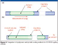
Figure 4
In the static coating method, depicted in Figure 4b, the entire column is filled with a solution of the stationary phase dissolved in a volatile solvent having a concentration appropriate for the desired film thickness. Here, the film thickness is proportional to the concentration of the stationary phase in the solvent and the diameter of the tubing. Unlike the dynamic method of coating, for static coating, the column is completely filled from end-to-end with the phase solution. Then, one end is sealed. The other end is connected to a vacuum pump and the solvent is evaporated from that end of the column at a prescribed temperature. Precise temperature control is required to achieve the optimum coating efficiencies. As the solvent evaporates, the front retreats backwards down the column leaving behind a coating on the wall. Once all of the solvent has evaporated, the stationary phase is all that remains in the column. The rate of evaporation is very important; if the vacuum or the temperature is too high, then the solvent within the polymeric film can "bump" leaving behind a nonhomogeneous layer and an unacceptable column. The static coating process takes much longer than the dynamic coating process but it generally is thought to be more reproducible and is the method commonly used for coating WCOT capillaries.
Using the previously described dynamic or static coating processes, the stationary phase can be immobilized or cross-linked in situ. This process must be performed in an oxygen-free environment to ensure the development of a stable, inert phase. In another approach, stationary phases that are polymeric can sometimes be formed on the wall surface by first depositing the monomers on the wall and then initiating polymerization either by heat or with an appropriate catalyst. Either the dynamic or the static process can be used. This process locks the stationary phase on the inner wall and immobilizes it. In general, techniques used for immobilizing the stationary phases also are highly proprietary and nothing is published or patented by companies that manufacture the columns. They are considered to be trade secrets.
Whatever process is used for coating, it is important to control the phase ratio (β) regardless of the column's inner diameter. From equation 1, one can see that β is controlled by the column radius:

where Vm is the volume of mobile phase, Vs is the volume of the stationary phase, r is the radius in micrometers, and df is the stationary phase film thickness. For column dimensions of 30 m × 0.53 mm, 3.0-μm df, and 30 m × 0.32 mm, 1.8-μm df, the phase ratio is 44. So, if column dimensions are changed or the radius is of the tubing is found to be different because of uncontrolled variations in the column internal diameter, retention time will change. To maintain the same elution order and obtain the same chromatogram, adjustments must be made in the phase ratio. For example, in Figure 5, the two chromatograms can be successfully reproduced on two different column dimensions with the same stationary phase by controlling the film thicknesses according to equation 1. For this reason, the column inner diameter should be measured at various locations along its length to ensure that the diameter is consistent. If there are inner-diameter differences between different columns, then the phase ratio should be adjusted by modifying the film thickness to maintain constant β. This will ensure consistency of the results. A typical tolerance of capillary tubing is +/- 6 μm, which is only a 1.1% variation for a 0.53-mm column but a 2.4% variation for a 0.25-mm column. So, proper adjustment is essential when using modern electronic pressure control where retention time precision is to third decimal place.
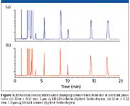
Figure 5
Once the stationary phase is bonded or immobilized, any unreacted polymer must be removed by thoroughly rinsing of the interior of the column with the appropriate solvent. Then, the solvent must be removed from the stationary phase itself by slowly heating the column with an inert gas flowing through it. Too rapid heating can cause bumping problems and ruin the column, so patience is required. As a final step, the column is heated to its upper limit with oxygen-free gas flowing through it to ensure that it is ready for final test.
Quality Control Testing
Despite all the advances made in manufacturing capability and reproducibility, the instrumentation requirements and user needs continue to push the envelope. Thus, it is important to check the performance of each and every column with test probes that are meaningful. The quality control department of every manufacturer plays a key role in ensuring that the columns shipped meet both the published and the internal specifications. The primary benefit of rigorous quality testing is to provide proven column-to-column performance in all respects which allows analysts to develop methods with confidence that the chromatographic performance of the capillary column is not a significant variable in overall system performance now or in the future. For example, Table III provides a set of test criteria that allows a user to have confidence that his or her particular compounds should perform consistently over the life of the assay. Obviously, it is not feasible for the manufacturer to check each column with each customer's actual sample but by a judicious choice of test probes that measure these factors, one can be assured that his or her compounds will behave consistently.

Table III: Typical performance criteria for a GC capillary column
Table IV provides a list of typical classes and typical compounds used to test the performance characteristics of a typical capillary column. The well-advised chromatographer should be aware that no one set of probes is adequate to test all columns for all application types. A set of test probes for a nonpolar–high temperature phase most likely would not be the best probes for testing a phase that has strong dipole interactions and a relatively low upper temperature limit. For very demanding applications, the analyst might be interested in finding a column that has the best inertness for his or her target compound list. For this analyst, a more rigorously tested column might be what is required. For example, a "premium" column (for example, a mass spectrometry [MS] phase) will likely have more test probes and perhaps stronger active compound probes in the test mix compared to the "standard" column of similar design. Premium and "specialty" application columns (for example, semivolatiles or PONA columns) also can have a second QC test that has tighter specifications for analytes found in the target list of the application for which that the column is intended.

Table IV: Classes and representative test probes for column characterization
In all cases, columns should be tested using isothermal conditions, a more rigorous test than temperature program runs which tends to sharpen peaks and hide problems. A typical column test data sheet with accompanying chromatogram is depicted in Figure 6. Test compounds are clearly identified and the test criteria are shown with rather demanding, but realistic requirements. Column efficiency is measured in plates per meter for a well-retained compound (pentadecane) with a k value greater than 5, not with a low k value. Figure 7 shows the effect of k value on efficiency. Choosing a low k value (for example, 2) clearly enhances the plate count and is not a true test of column efficiency since these compounds spend very little time in the stationary phase. In real life most compounds will have much larger k values as well. The actual measured column inner diameter is shown so that appropriate adjustments to this parameter for proper electronic pressure control settings can be made.
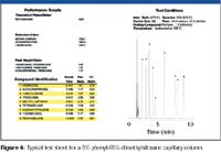
Figure 6
Selectivity measurements via retention indices are provided for three different probes with three different functional groups. Inertness is measured with probes (Figure 8) that possess non-sterically hindered functional groups that allow maximum interaction between the stationary phase and the capillary walls. Choice of a sterically hindered phenol such as 2,6-xylenol would not be an adequate probe to reveal active sights on a capillary wall and would give the user a false sense of security. A better measure of inertness is the peak height ratio between a hydrocarbon and a compound with a polar functional group. Hydrocarbon peaks will be unaffected by an active surface but if a polar compound strongly interacts with the surface, it will show a decrease in peak height revealing a problem of sample loss and recovery. The peak height ratios for 1-dodecanol/tetradecane, 1-decylamine/tridecane, and 4-chlorophenol/tridecane are good measures of column inertness. Tailing factors also can provide evidence of column inertness but the peak height ratio has proven to be a more reliable measurement since it measures a variety of functional probes. A bleed profile also is run by temperature programming a column from 50 °C to its maximum operating temperature. For a typical GC–MS 5% diphenyl–95% dimethylpolysiloxane column, bleed specification is below 4 pA using a flame ionization detector over this temperature range.
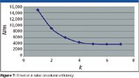
Figure 7
Testing for Specialty Columns
For application-specific columns such as pesticide columns or semivolatiles columns for environmental methods, columns are usually tested with the compounds that the column will be used for using a detector typical of that application. For example, for chlorinated pesticides, an electron-capture detector would be used along with a sample containing the Environmental Protection Agency's Method 608 or 8081A list of CLP test pesticides. For dual columns (primary and confirmation column) such as those used in blood alcohol analysis, each column would be tested individually to ensure that it meets the demanding separation criteria such as the ethanol–acetone pair. Many manufacturers will prepare custom columns for those users who have special needs. The columns will usually sell for a slightly higher price because of the special handling conditions.

Figure 8
Conclusions
Modern day GC WCOT capillary columns have evolved to provide trouble-free operation and reproducible and reliable separations. With rigidly controlled manufacturing and quality control procedures, the worry of taking a column out of the box and having it not perform as expected is minimized. As long as the manufacturing process is followed according to standard operating procedures, column-to-column reproducibility problems are generally a thing of the past. Nevertheless, most columns still are tested thoroughly with demanding test probes and a data sheet is shipped with each column to ensure the user that the columns should meet his or her expectations.
Acknowledgment
The authors would like to thank Joseph Harland of Agilent Technologies, Wilmington, Delaware for his review of the manuscript and for his helpful comments.
Allen Vickers and Daron Decker are both employed by Agilent Technologies' Columns and Supplies Division. Allen Vickers is a manufacturing applications chemist located the J&W Scientific Columns manufacturing site in Folsom, CA, and Daron Decker is a field applications chemist located in Houston, TX. Both have a strong interest in GC column technology and have many years of GC capillary column applications experience.
Ronald E. Majors "Column Watch" Editor Ronald E. Majors is business development manager, Consumables and Accessories Business Unit, Agilent Technologies, Wilmington, Delaware, and is a member of LCGC's editorial advisory board. Direct correspondence about this column to "Sample Prep Perspectives," LCGC, Woodbridge Corporate Plaza, 485 Route 1 South, Building F, First Floor, Iselin, NJ 08830, e-mail lcgcedit@lcgc-mag.com.
References
(1) R.E. Majors, LCGC 24(8), 742–753 (2006).
(2) R.D. Dandeneau and E.H. Zerenner, High Resolut. Chromatogr. Chromatogr. Commun. 1, 351–356 (1979).
(3) K. Grob and G. Grob, J. Chromatogr. 347, 351–356 (1985).
(4) V.G. Berezkin and J. de Zeeuw, Capillary Gas Adsorption Chromatography (Huthig, Heidelberg, 1996).
(5) R.E. Majors, LCGC 21(10), 960–966 (2003).
(6) S. Griffin, LCGC 20(10), 928–938 (2002).
(7) R.P.W. Scott, Chrom.Ed. Series
New Study Reviews Chromatography Methods for Flavonoid Analysis
April 21st 2025Flavonoids are widely used metabolites that carry out various functions in different industries, such as food and cosmetics. Detecting, separating, and quantifying them in fruit species can be a complicated process.
University of Rouen-Normandy Scientists Explore Eco-Friendly Sampling Approach for GC-HRMS
April 17th 2025Root exudates—substances secreted by living plant roots—are challenging to sample, as they are typically extracted using artificial devices and can vary widely in both quantity and composition across plant species.
Sorbonne Researchers Develop Miniaturized GC Detector for VOC Analysis
April 16th 2025A team of scientists from the Paris university developed and optimized MAVERIC, a miniaturized and autonomous gas chromatography (GC) system coupled to a nano-gravimetric detector (NGD) based on a NEMS (nano-electromechanical-system) resonator.
Miniaturized GC–MS Method for BVOC Analysis of Spanish Trees
April 16th 2025University of Valladolid scientists used a miniaturized method for analyzing biogenic volatile organic compounds (BVOCs) emitted by tree species, using headspace solid-phase microextraction coupled with gas chromatography and quadrupole time-of-flight mass spectrometry (HS-SPME-GC–QTOF-MS) has been developed.


