Variable Retention Times — A Case Study
LCGC North America
This troubleshooting study of a problem of retention time variation provides a good example of how to track down the source of a problem and how to speculate on probable cause.
How do you identify the cause of unstable retention times?
Three readers from Central Europe sent me an e-mail inquiry regarding a problem of retention time variation that was in excess of the system suitability requirement for the method, 2% relative standard deviation (%RSD). Although the speculated source of the problem has not been proven by replacing a suspected faulty part, enough data were presented to make this a good example of how to track down the problem source and to speculate on the probable cause, so we joined forces for this installment of "LC Troubleshooting."
Go to Trusted Standard Conditions
After finding that system suitability didn't pass, the conditions were changed to standardized column test conditions. The goal is to be able to test the liquid chromatography (LC) system independent of the method. A new 150 mm × 4.6 mm C18 column packed with 5-μm diameter particles was installed in the system. The test conditions for this column were a mobile phase of 60:40 methanol–water at a flow rate of 1 mL/min and a column oven temperature of 25 °C. The test sample comprised a mixture of analytes that included methyl benzoate. The LC system was a four-solvent system that uses low-pressure mixing. In this design, the mixture of the four solvents (A, B, C, and D) is controlled by proportioning valves that feed the solvents in pulses into a mixer (a diagram of this is shown in Figure 1b of reference 1). For the present experiments, the solvent inlet tubing for the A and C channels was placed in a bottle of high performance liquid chromatography (HPLC)-grade water, and the solvent inlet tubing for B and D was placed in a container of HPLC-grade methanol.

Figure 1: Gradient step test. Gradient ramp from 0% to 100% followed by steps back to 80%, 60%, 40%, 20%, and 0%, run on channels A/B and C/D. Mobile-phases A and C are water, B and D are 0.1% acetone in water, run at 1 mL/min. Red dashed lines added to highlight step size differences (horizontal) and gradient nonlinearity (diagonal). See text for details.
To test within-day and between-day variability, runs were made over three days, as summarized in the top section of Table I; runs were made with the A and B solvents or with C and D solvents. Injections of the test mixture resulted in a peak in every run at 1.25 min, corresponding to uracil. Additionally, a peak was seen at ~10.1 min for methyl benzoate, but the %RSD of the retention time for the four runs of Table I varied from 0.30% to 2.49%; all combinations of between-day variability ranged from 0.79% to 1.87%. From a pass–fail standpoint, only the C/D run on day 2 failed the system suitability requirement of 2%. However, the method historically had performed with <0.5% RSD for these tests.

Table I: Retention times for methyl benzoate (in minutes)
What is most worrisome here is the inconsistency of the results. For example, the A/B test on day 1 passed, but the RSD was approximately threefold larger than on day 2. Similarly, RSD for the C/D test on day 2 was more than eightfold larger than that on day 3. You might justify rejecting the first run on day 1 (10.36 min) because of insufficient equilibration, although it doesn't qualify as an outlier using Dixon's Q test. With this point dropped, the RSD is reduced to 0.29%. However, you can't apply the same logic to the C/D test on day 2, where the high and low values are approximately duplicated.
Before calling for additional help, a mobile phase of 60:40 methanol–water was hand-mixed and the retention checks for n = 6 injections were repeated twice. In both cases, the maximum difference between retention times was 0.04 min. This indicates that the pump is operating properly and the retention times are stable when a fixed mobile phase composition is used. A problem with the on-line mixing system is the most likely cause, so at this point, the instrument manufacturer was contacted for some help, as described in the next section.
Gradient Step Test
The manufacturer's service technician ran the gradient step test shown in Figure 1. This is slightly different from the 10% steps that normally are recommended in "LC Troubleshooting," but there is nothing wrong with this approach. The column is removed and replaced with a piece of capillary tubing — approximately 1 m of 0.125-mm i.d. tubing works well. The A-reservoir is filled with HPLC-grade water and the A and C solvent inlet lines are placed in it. The B-reservoir is filled with HPLC-grade water containing 0.1% acetone and the B and D lines are placed in it. The ultraviolet (UV) detector is set to 265 nm, where acetone absorbs strongly. A method is programmed with a gradient of 0–100% of the acetone solvent in 15 min at 1 mL/min, followed by 5-min steps at 100%, 80%, 60%, 40%, 20%, and 0% using either channels A and B or C and D. This method generates the profile shown in Figure 1. The gradient is used to test mixing linearity and the steps are used to check proportioning accuracy. The manufacturer's acceptance criteria are that each step must be within ±2% of the set point; other sources often recommend using ±1% for this test, but in the present case either acceptance limit passes.
The step-test results were calculated by manually measuring the step heights in Figure 1 and normalizing these between the 0% and 100% values; these agree within 0.1% of the manufacturer's test measurements using the data system. You can see that all the steps pass within the ±2% (or ±1%) criteria. However, a visual examination of the data of Table II shows that the results for the intermediate steps using C/D are consistently lower than the A/B steps by 0.2% to 0.5%; you can see this highlighted by comparing the step heights to the horizontal dashed lines in Figure 1 (offset from the tracing for clarity). This variation may or may not have any significance.

Table II: Step-test results from Figure 1
Gradient Linearity
The test results of Figure 1 also allow us to examine the gradient for linearity. A diagonal dashed line parallel to the gradient has been added for both the A/B and C/D gradients in Figure 1. With this reference, it is easy to see that there is distortion in both gradients in the 0–30% region, and worse for the A/B trace. This kind of performance is reminiscent of an earlier case study (2), in which a malfunctioning proportioning valve caused ripples in an otherwise straight gradient trace. In that case, an additional test, the gradient proportioning valve (GPV) test illuminated the problem.
Gradient Proportioning Valve Test
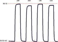
The GPV test is easy to run and can be performed with the same instrument setup as the step and linearity tests run for Figure 1. In this case, the A and C solvent lines are placed in the water reservoir; the B and D lines are in the acetone-water reservoir and the flow is set to 1 mL/min. The program cycles between 50:50 A/C (which is 100% water) and the various combinations of 90% water and 10% of the water-acetone mixture, as shown by the labels in Figure 2. Because the baseline is always A/C, it should be level (see dashed red line added for reference). Similarly, because each step is 90:10 water–water-acetone, all the steps should be the same height. An acceptance criteria often used allows the maximum difference in step heights of no more than 5%, but usually something isn't right if anything more than ~3% is observed. A summary of the results obtained from the GPV test of Figure 2 is contained in Table III. You can see that the A/B and C/B steps have the identical maximum value with reference to the red dashed line added at the top of Figure 2. If we use this as 100%, the A/D step is 4.6% low and the C/D step is 3.4% low. When evaluating the GPV test, usually two steps are off. In the example in reference 2, the A/B step was low and the A/C step was high. In the present case, the A/D and C/D steps are low. Most likely, the problem source is associated with the solvent line that is common between the two problem steps — D in the present example.

Figure 2: Gradient proportioning valve (GPV test) run at 1 mL/min. Baseline is 50:50 A/C, where A and C are 100% water. Steps are 90% water blended with 10% of a waterâacetone mixture with the various proportioning valve combinations listed. Dashed red lines added to allow comparison of step heights. See text for details.
In addition to the 1-mL/min GPV test detailed above, the GPV test was repeated at 0.5, 1.0, and 2.0 mL/min. The results were not consistent with those of Figure 2. In the worst case, the A/D and C/D steps were 12–13% low and in the best case, only the A/D step was low by 3%, whereas the remaining steps were identical. All these data point to a problem with the solvent proportioning system.

Table III: Gradient proportioning valve results from Figure 2
As a final check before making any hardware changes, a siphon test was run. In this test, each solvent line is removed from the proportioning manifold and allowed to flow freely by siphon action (the reservoirs must be mounted above the tube outlet). A good acceptance criteria is to see a siphon flow of at least 10 times the maximum desired flow rate. For example, most LC systems are operated at 2 mL/min or less, so 20 mL/min should be flowing through by siphon action. If the flow is less than this, check for restrictions or a blocked frit in the reservoir; correct this and repeat the GPV test. In the present case, all four solvent lines delivered 21–24 mL/min under these conditions, so there was no indication of restrictions in the lines.
Interpreting the Results
Although the step test passes acceptance criteria, all the other data point to a problem with the mobile-phase preparation system. Retention time changes are erratic, the gradient is visibly nonlinear, and the GPV test marginally passes in only three of four tries. Because the GPV test most commonly gives low results for both of the combinations involving the D solvent, the D proportioning valve is likely to be defective. The only failure of the A/B combination was in the retention checks and if the very first injection was dropped, the rest of the results would pass. However, the initial retention problem with system suitability failure for the analytical method used the A/B channels, so this implies that failure isn't a one-time factor for A/B, either.
The proportioning valves are magnetically controlled solenoid valves that open and close a flexible polymer membrane to allow solvent to flow to the proportioning manifold. The "rise time" — that is, the time for the valve to open — is very carefully matched between the four valves so that the system works properly. This makes it difficult to change just one proportioning valve, so a factory rebuild or replacement is the best choice. It is possible that one or more of the valve seals could be leaking. If you are handy at repairs, you could take the proportioning manifold apart and clean the seals and reassemble it to see if it fixed things. There is little risk with this if the only other option is to replace the manifold — if you fix it, you're in luck; if you break something, you had to replace it anyway. But before doing that, it would be prudent to check the warranty on the LC system and see if you could get the manifold replaced under warranty.
Conclusions
This case study was a very specific problem, but it makes a good platform for applying general troubleshooting principles. First, the problem was confirmed as happening more than once before further investigation was done. Next, the LC system was isolated from the method conditions by running standard column test conditions on a known good column. Different combinations of solvent mixtures were used to see if failed results pointed to one or more solvent lines, with enough replicates made that statistical variation could be measured.
After the problem was confirmed to occur fairly regularly, a standard gradient step test was performed to check the solvent proportioning system for proper operation. Although the step test passed, the gradients were distinctly nonlinear. This prompted a more detailed test of proportioning, the GPV test was run several times. With these results in hand, it is time either to call a service technician for repairs or to order a replacement proportioning manifold.
References
(1) J.W. Dolan, LCGC North Am. 31(6), 456–463 (2013).
(2) J.J. Gilroy and J.W. Dolan, LCGC North Am. 22(10), 982–988 (2004).
Katerina Naumoska, Dr. Alen Albreht, and Dr. Irena Vovk work in the Laboratory for Food Chemistry at the National Institute of Chemistry in Ljubljana, Slovenia, and at the EN-FIST Center of Excellence in Ljubljana, Slovenia. Their primary field of interest is method development for the determination of natural and pharmaceutical compounds by chromatographic and mass spectrometric techniques.

Katerina Naumoska

Dr. Alen Albreht

Dr. Irena Vovk
John W. Dolan "LC Troubleshooting" Editor John Dolan has been writing "LC Troubleshooting" for LCGC for more than 25 years. One of the industry's most respected professionals, John is currently the Vice President of and a principal instructor for LC Resources, Walnut Creek, California. He is also a member of LCGC's editorial advisory board. Direct correspondence about this column via e-mail to John.Dolan@LCResources.com

John W. Dolan

Extracting Estrogenic Hormones Using Rotating Disk and Modified Clays
April 14th 2025University of Caldas and University of Chile researchers extracted estrogenic hormones from wastewater samples using rotating disk sorption extraction. After extraction, the concentrated analytes were measured using liquid chromatography coupled with photodiode array detection (HPLC-PDA).
Polysorbate Quantification and Degradation Analysis via LC and Charged Aerosol Detection
April 9th 2025Scientists from ThermoFisher Scientific published a review article in the Journal of Chromatography A that provided an overview of HPLC analysis using charged aerosol detection can help with polysorbate quantification.
Removing Double-Stranded RNA Impurities Using Chromatography
April 8th 2025Researchers from Agency for Science, Technology and Research in Singapore recently published a review article exploring how chromatography can be used to remove double-stranded RNA impurities during mRNA therapeutics production.


