Ultrafast HPLC: Different Approaches to Increased Throughput
LCGC Europe
Over the years, LC instrumentation has undergone continuous development in pursuit of greater performance. More recently, the focus of progress has been on shorter run times, as a direct response to greater user demand to perform faster chromatographic analyses, particularly for their LC–MS applications. This has led to separations on short (30–50 mm) columns with a small internal diameter (i.d. ~2.0 mm), packed with small particle size phases (1.5–3.0 μm). The trend for smaller column particle size has now reached a practical limit on current hardware and innovative technological solutions for further gains in performance are required. Several manufacturers offer fast LC instruments designed for greater productivity, while maintaining low carryover, high sample capacity, resolution and reliability. With ultra-fast run times of under 1 minute, these companies have achieved increased throughput using contrasting technological approaches. Here we examine the background to this current trend,..
The increasing popularity of liquid chromatography (LC) for quantitative separation, identification and purification of compounds in widespread applications reflects the benefits of the technique, including its high resolution, broad application and scalability from pure analysis to preparative purification of compounds. Although the discovery of LC is generally dated back to 1903, when M.S. Tswett used a polar column to separate plant pigments (recently reviewed by Berezkin 2001),1 the development of modern LC-based techniques largely began in the 1960s. Today, LC is fundamental to a vast number of global industries, from forensics to food safety, pharmaceuticals to protein research, and the demand for increasingly high resolution and productivity has driven a number of technological advances over recent years.
Regardless of the application, the speed and resolution of the separation are critical parameters of the LC system's performance. These are affected by many factors that can be subdivided into two main categories — those which directly influence the actual separation chemistry and those associated with system design. The former includes the choice of column (length and i.d.) and its packing material (particle size, size distribution, pore size, pore size distribution and chemistry); mobile phase; temperature and flow-rate (velocity). The latter also includes the column (physiochemical properties of column walls and frit as well as how well the particles are packed); tubing and flow path (tubing i.d., dwell volumes, materials, switching valves etc.); pump design (flow-rate, pressure tolerance and pulsation); sample injector (design, speed of injection, carryover and dwell volume); detectors (flow cell design, response time, acquisition rate etc.); and even the data system.
Much of the progress that has been made in the design of LC systems over the past few decades has been driven by improvements in column technology. As we know, the column is key to any LC system as it contains the stationary phase that actually enables the separation, and the important parameter here is resolution, R where

In turn, R can be affected by influencing the three contributory factors — retention (k'), separation (α) and efficiency (N). The retention (expressed as the capacity factor, k') is primarily influenced by the stationary and mobile phases, but is also affected by temperature — increasing temperature decreases k' (log k' is inversely dependent on temperature), although this does not necessarily result in a poorer separation. The separation factor (α) is also influenced by these three things, which all fall into our first class of parameters, those influencing the separation chemistry. However, column efficiency, N, (expressed in theoretical plate number) is primarily influenced by six factors: packing size and size distribution; surface area; pore size; mobile phase velocity; mobile phase viscosity; and temperature.
Three of these parameters (particle size/distribution, surface area and mobile phase velocity) are in our first category of directly influencing the separation, but are generic physical parameters under our control, and so may be generically optimized for many separations. As the column efficiency increases, analyte components will elute in a smaller volume of the mobile phase, observed as narrower peaks on the chromatogram, which are, therefore, easier to resolve from one another.
Of these parameters, the size of the particles used to pack the column has become a particular focal point, because the column efficiency increases as the particle size (and range of size distribution) decreases. The concept is not new: in 1941, Martin and Synge2 postulated that, "The smallest height equivalent of theoretical plate (HETP) should be obtained by using very small particles and a high pressure difference across the length of the column." An in-depth discussion of factors affecting column efficiency was given in a recent edition of LCGC Europe's "Column Watch",3 and here we will only briefly recap the most important points. The relationship of a column's HETP (H) with the mobile phase flow velocity is described by the van Deemter equation (Equation 2).

A, B and C are the coefficients for eddy diffusion, longitudinal diffusion and resistance to mass transfer, respectively; μ is the linear velocity through the column, in cm/s. In other words, decreasing the contribution made by these factors to the plate height increases column efficiency and is desirable. The A term is generally found to be proportional to the diameter of the stationary phase particle (dp) while the C term is proportional to dp2 . Therefore, decreasing particle size significantly reduces the minimum plate height, allowing operation at higher flow velocities (μ) without sacrificing efficiency. It should be remembered that van Deemter curves only apply to isocratic separations and not to gradient analysis, though they can give general indications of column performance in gradients by using average peak width.
"Fast" LC and Small Particle Packings
As Martin and Synge predicted, LC technology has progressed through using columns packed with particles of decreasing size, leading to greater column efficiency through smaller HETP and faster optimum velocities (Figure 1). When LC was originally being developed, the particles used were relatively large and irregular, ranging from 20–50 μm in size. Over time, the particles have become smaller and uniform in shape: In the 1970s, 10 μm particles were available; in the 1980s, 5 μm and, in the 1990s, 3.5 and 3 μm particles and so on, up until the current situation today with a wide variety of sub-2 μm particles.
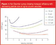
Figure 1
Increasing the efficiency of the column by using smaller particles also allows faster LC cycle times through the use of shorter, narrower columns (30–50 mm long and 2 mm i.d.) operating at higher velocities, resulting in greater productivity and dramatically increased throughput. Smaller column volumes result in less dilution of the analyte in the column, providing the benefit of greater sensitivity in concentration-based detectors (the great majority of current LC detectors fall into this category). Fast LC methods can be developed in hours and validated in days rather than weeks and the shorter analysis times can translate to a 50–80% reduction in solvent use (even at higher flow-rates), which lowers the cost of purchase and waste disposal, especially when the ratio of waste:number of samples processed is considered.
Using smaller particles, however, is not without its limits: The backpressure generated across the column is inversely proportional to the square of the particle size, so if the particle size is halved then the pressure increases by a factor of four, making it difficult to decrease particle size and increase the velocity without specialized hardware. Practically, this makes it hard to use longer columns for increased resolution with fast LC (especially in conventional LC instruments where pressures are limited to <6000 psi), therefore, shorter columns are optimal, and even in specialized equipment pressures rapidly become prohibitive (a 50 × 2 mm, 1.7 μm column running at 1 mL/min generates a backpressure of ~15000 psi). This places a limit on the maximum plate number that may be achieved by using small particle columns.
It also means the column may not be running at its optimal velocity, as adding column length to increase the number of theoretical plates would mean slowing the linear velocity and, therefore, losing both efficiency and the high-speed performance (as a result of increased column volume and lower flow). For example, a short (50 mm column) with 2 μm particles has a similar performance to a longer (150 mm), 5 μm column. While the short 2 μm column can run the analysis faster, even a specialized LC system will be at its pressure limits (~15000 psi) so the resolution cannot be improved by adding more column length without decreasing flow-rate (velocity), whereas the 150 × 5 μm column may be easily lengthened to 25 cm to provide this resolution within the pressure tolerance of the system.
As technology has yet to reach the level where we can alter the laws of physics, higher operating pressures will mean greater wear on LC components and consumables. This may or may not be a price we are willing to pay for our increased throughput and, again, the cost of maintenance and consumables expressed as a function of results processed may give a more realistic view of this.
However, the operability and ease of maintenance of an LC system are other considerations and are more subjective and based on user experience. Instrument reliability may be compromized, causing a reduction in accuracy, precision and reproducibility. We should also bear in mind that the size of the particles we are now dealing with inhabit a world that is different from the one we are familiar with: A 1.5 μm particle is about the same size as common bacteria. The potential to block these columns is obviously higher than with larger particles, so dust, microparticles from the pump, injector and sample, mobile phase buffers and even bacteria should be excluded from the flow stream. Although on-line, precolumn filters can minimize this problem, they can introduce additional precolumn dead volume into the flow path and need to be regularly cleaned or replaced, increasing down-time and maintenance. The flow path (one of the system design parameters) for smaller particles is also more critical to preserve resolution, meaning that specialized tubing and connectors are required; small voids and dead volumes within the tubing have a much more negative effect on peaks of a few microlitres in volume and, again, separation reproducibility can be reduced.
Specialized Equipment for Small Particle Packings
While a number of companies, for example Jasco Europe SRL (Cremella, Italy), have developed "ultra"-pressure pumps in the past, these have largely remained unused in mainstream LC, because other components able to tolerate these high pressures or optimized for the resulting narrow peaks were not available as a complete system. In 2004, Waters (Milford, Massachusetts, USA) announced the Acquity system, which was optimized for use of 1.7 μm packed columns working at pressures of up to 15000 psi — about three times the limit of a "standard" LC system. This system has been specifically designed to exploit these small particle, high velocity and, hence, high efficiency areas of the van Deemter equation. It uses pumps capable of tolerating very high pressures with low dwell volume, together with small i.d. capillaries, specialized high-pressure fittings and fast acquisition rate and response detectors. To demonstrate the ability of this type of system, a separation of alkylphenones may be performed in under 1 minute (Figure 2).
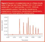
Figure 2
Such a system, however, has characteristics unusual to many LC users. As the tubing is designed for low dispersion, its very small i.d. means that backpressures are high even without a column installed. The pumps are designed to operate at very high pressures only within a narrow flow-rate range (<2 mL/min), the column oven is relatively small (accommodation of a single column of ≤15 cm) and the injector system is relatively complex and can take up to 60 seconds to inject a sample and perform a dual-wash cycle. Because it is an integrated system designed for fast LC (and primarily LC–MS and LC–MS–MS) analyses, it has limited options in terms of flexible column switching, detection techniques and column stationary phase.
Despite these issues, several other manufacturers have designed systems that are capable of operating at higher pressures, including Jasco's X–LC system, the Agilent 1200 RRHT (Agilent Technologies, Waldbronn, Germany), Dionex Ultimate 3000 (Dionex, Sunnyvale, California, USA) and Thermo Accela (Thermo Fisher Scientific, Waltham, Massachusetts, USA). These systems are able to operate at maximum pressures of between 7000 and 15000 psi. The main difference between most of these systems and the Acquity system is their modular nature, which allows greater flexibility, but also has the potential to introduce inappropriate dead volumes and voids.
Are We Asking the Wrong Question?
A topical question from someone looking to purchase an LC system is: "What pressure can your system run at?" In the majority of instances, this is not really the question that the purchaser wants answered; in fact, he wants to know if the system will solve his current analytical problem, whether that involves increased resolution, increased productivity, ease of use and so on. This may, of course, involve using a system that runs small columns packed with sub-2 μm particles running at very high pressures, but it is not a foregone conclusion.
So how else can we achieve high efficiency without generating increasingly high pressures? As discussed previously, as the particle size decreases, the backpressure increases at a greater rate than the corresponding increase in column efficiency (Figure 3). Therefore, it is possible to find an optimum area of particle size where the best balance between efficiency gain is reached, without the disadvantageous increase in backpressure.
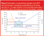
Figure 3
As shown in Figure 3, the region between 2 and 3 μm particles is especially interesting, as the van Deemter curves produced are flat enough to allow high velocity, but the lack of excessive pressure allows more absolute plates to be added by extending column length. This will allow high-efficiency separations to be run at more conventional pressures, but also opens up an area of even higher resolution separations based on longer columns.
To demonstrate this, we could phrase our analytical question thus — what is the most efficient column I can use for a given set of conditions? For example, I have a system with a pressure limit of 300 bar — what would be the best column to combine speed and efficiency for the separation of a pair of compounds? Choosing a 1.8 μm particle column of small dimensions (2.1 × 50 mm) might be our first choice, however, if we use a longer column packed with slightly larger 2.2 μm particles (in the optimization region described above), we can achieve a better, faster separation at a lower pressure (Figure 4). This is because our absolute plate count on the larger particle packed column is higher, while the column volume is still low enough and velocity high enough to produce a fast separation.
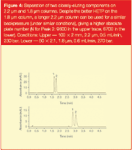
Figure 4
Even with 3 μm columns, highly efficient separations similar to those run under very high pressures can be achieved (Figure 5). While this is an argument for producing "UPLC-like" separations on a standard LC system, it is also applicable to higher-pressure systems — using a longer 2.2 μm column on a UPLC system should produce a better separation than a shorter 1.8 μm column.
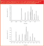
Figure 5
Of course, the logical extension to this argument is to use much longer columns of a larger particle size — if all other parameters remain constant, it should be possible to run a 500 × 2 mm column packed with 5 μm particles. Even at the high linear velocity favoured for sub-2 μm particles (and therefore substantially sub-optimal for the 5 μm particle), we should have about twice the absolute number of plates as the 50 × 2 mm, 1.7 μm column. Running at an optimum velocity for the 5 μm particle, we could use a 1.5 metre column, giving a plate count in the region of five times higher than the 50 × 2 mm column! Of course, this is not really practical for high throughput work because of other considerations; the time required to elute components, especially at optimum velocities for instance, would be prohibitive (around 100 times slower than a 50 × 2 mm, 1.7 μm column).
It does illustrate, however, that by minimizing particle size and trying to cram as much as possible into a very small column, we may actually be putting an upper limit on what is possible with our system. Columns in the 2–3 μm range allow much higher absolute plate numbers without compromising speed to an excessive degree — a 100 × 2 mm, 2.2 μm will produce a pressure equivalent to that of a 50 × 2 mm, 1.7 μm column running at the same linear velocity, but has about 150% of the theoretical plates. Once again, we have to bear in mind what we are trying to achieve — there is a point when the speed of a separation compromizes the resolution, rendering the analysis a rather pointless exercise. What we should do is try to balance the analytical requirements of speed, resolution and capacity to optimize the solution we use.
The other advantage of using particles in the 2–3 μm range is that columns with these phases are easier to pack well and reliably, and are affected less by tubing dead volume, small voids, particles and so on. This makes reproducibility and robustness almost identical to that expected in standard LC. They may be used for so-called "regular" LC as well as fast analysis, depending on the analytical conditions (velocity, temperature etc.). In addition, we do not lose anything in terms of sample capacity, an often overlooked area of fast LC separations — speeding up analysis is one thing, but if a method is to be used preparatively it also needs to be scalable, something not currently practicable with very high pressure separations.
Temperature as an Active Separation Parameter
Concentrating on particle size is one way of affecting column efficiency but, as we have seen, not the only one. Temperature has a significant effect on efficiency, causing an estimated 1.5% increase for every 1 °C increase in temperature. An increased temperature reduces the viscosity of the mobile phase, improving mass transfer (so reducing the C term in van Deemter's equation). This has the effect of lowering and flattening a column's van Deemter curve towards higher velocities, in exactly the same way produced by using smaller particles. Unlike smaller particles, however, increased temperature has the benefit of lowering the backpressure in the column and, in turn, this allows the flow-rate to be increased even more, allowing high resolution and high speed separation simultaneously, at "standard" LC pressures.
At this point it is useful to remember that column efficiency is only one factor in the resolution equation, which is the
all-important parameter in LC. Moreover, efficiency (N) is under a square root, so doubling the efficiency only results in a 41% increase in the contribution to resolution. Therefore, to double the contribution, efficiency would have to be increased by a factor of four. Increased temperature also decreases the capacity factor (k') by up to 1–2% temperature increase, as well as affecting the selectivity (α).
However, increasing the temperature can also be problematic. With higher temperatures (>60 °C), internal column temperature gradients can occur and these will manifest as poor peak shape and peak "splitting". To avoid this, the mobile phase and sample need to be preheated before entering the column. Secondly, the flow path after the column must either be compatible with high temperatures or feature a method of cooling the mobile phase back to "normal" temperatures associated with LC, as most detectors are not designed to handle high temperature liquids (although higher temperatures may actually be beneficial to MS ionization). Thirdly, thermally labile components may degrade on-column, and this is often the primary concern of those unfamiliar with using higher temperature in separations. Practically, however, thermal degradation of analytes does not seem to occur as much or as quickly as might be suspected.
The reasons for this are beyond the scope of this article, but the example of UHT treated milk should be considered, where thermally unstable proteins are not denatured by the very high temperatures used to sterilize the product. This is not an analogy, but illustrates the point that just because the temperature is elevated it does not mean degradation will occur. Finally, high temperature also lowers the polarity of water, so method transfer from lower temperatures will need development, because less solvent will be required for the separation, and this can actually be beneficial in reducing solvent consumption and disposal.
Several commercial systems now allow for routine fast LC operation at higher temperatures. The Shimadzu Prominence LC20 series (Shimadzu Europa, Duisburg, Germany) has high-temperature capability, as does the Agilent 1200 system released in 2006. Taking this latter system as an example, the 1200 SL oven has a temperature limit of 100 °C and features pre-column heaters to prevent thermal gradients and a post-column cooler to avoid heat damage to detectors. A high temperature separation of phenones run on a 1200 RRHT system at moderately elevated pressure is shown in Figure 6.
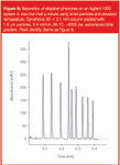
Figure 6
Other Considerations for Fast LC
So far, we have considered the mechanics of the separation in terms of how to achieve the highest possible resolution from our column. Other hardware parameters also contribute to the overall performance of LC systems, as mentioned at the start of this article. Generally speaking, for a system to be suitable for fast LC, the system should have minimal dwell and column volumes, a pump capable of accurately delivering solvent at appropriate linear velocities and detectors fast enough (both in data acquisition rate and response time) to properly capture the analyte peaks. Aside from these "chromatographic" parameters are the other design aspects of the system that are frequently overlooked, but may have a large impact on overall productivity.
A high performance autosampler is vital for achieving the most efficient LC, as the autosampler can be the major rate-limiting step in today's fast LC cycles. Until recently, most autosamplers would take a minute or more to inject a sample. With the demand of fast LC with run times of a minute or less to process thousands of samples, this autosampler injection time of a minute-per-sample is essentially halving the total productivity potential of the system. Some modern autosamplers, however, are capable of injection cycle times of as little as 10 seconds, significantly shortening the total cycle time, so improving throughput and productivity. An example of this is shown in Figure 7, where the total cycle time (injection-to-injection) of a gradient separation of phenones is just 23 seconds. The design of the autosampler is also critical to the level of carryover observed, which determines the amount of washing that has to be performed in-between injections and can affect the cycle time of the autosampler. In addition, the autosampler should be able to cope with the large numbers of samples that fast LC allows us to process, and ideally allow samples to be added to the system without stopping its operation. Table 1 compares some of the currently available system autosamplers.

Figure 7
Another frequently overlooked parameter in fast LC is the data system and its associated communication. We can think of this in terms of the time taken from when we click a mouse button on the PC activating our instrument to it actually starting that process. Likewise, after the run is finished, there is a finite time associated with the data capture and storage into a data file, before the next initialization is started.

Table 1: Comparison of several modern "high throughput" system autosamplers with a typical "standard" HPLC injector.
These may seem like insignificant things, and indeed in standard LC we never even notice them, but in fast LC we are working in different timescales. For instance, if we have a fast LC system that injects in 10 seconds, the communication to the instrument before and after the run may also be 10 seconds, which impacts our total cycle time. This is in an ideal world with fast PCs and direct communication; on a large network built of older (slower) PCs, this factor then becomes relatively large and will impact the theoretical maximum number of samples that may be processed on a system, even if in practice we do not approach that number on a daily basis. One blessing here is that at least this parameter is easy to measure — all you need is a stopwatch and your LC system.
Finally, we should examine the system reliability and the slightly less scientific parameter of "ease-of-use". Let us imagine we have an LC system that gives us a total cycle time of 2 minutes. If the system is in constant use, we can expect to process 30 samples an hour, or a potential 720 samples a day. If we start to rely on this potential (and few companies buy more systems than they actually need in today's business environment), then any downtime on the instrument means that samples start to stack up very quickly. Even with a 24 h service response and a first-time fix, hundreds, possibly running into thousands, of samples will become stacked up, waiting to be run.
This then also feeds into the ease-of-use of a system. If a user can quickly identify and resolve a problem, less downtime on the instrument is incurred. Ease-of-use is, of course, always a subjective parameter, but both it and the reliability of the system should be areas that are examined carefully, as they can potentially have a huge effect — what good is a system that runs your samples in half the time if its downtime is twice that of an existing system? This means the overall gains from the system are less than expected, and user confidence and "comfort" with the system are also affected.
Future Directions
It is an interesting time to be involved in analytical LC: Manufacturers are exploring new boundaries and approaching a developing market in different ways, including using ultra-high pressures, smaller particles, high temperature and a mix of these parameters. What the future direction will be is unclear at the moment, whether this will involve even smaller particles, longer columns of existing "standard" particles or sub-2 μm particles with even higher pressures, new monolithic technologies, new separation phases, very high temperatures or combinations of several of these technologies.
High temperature, for example, offers the possibility of removing organics from mobile phases completely, with high temperature gradients in 100% water (possibly heated directly using microwave radiation), and then use of a flame ionization detector (FID) for generic detection. This is an appealing approach, but there are many obstacles to overcome. Certainly initial forays into these areas4 have proved interesting (Figure 8), but at the moment they remain outside of the mainstream of LC. For how much longer this will be true remains to be seen.
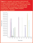
Figure 8
Summary
Today's chromatographers expect their LC systems to perform highly sensitive, reliable, high throughput separations. Over recent years, the performance of LC systems has been increasingly improved thanks to a number of technological advances, resulting primarily in better efficiency and faster analysis times. However, the trend for using smaller and smaller particle sizes has now reached a practical limit and manufacturers have taken different ways forward to provide answers to the question of providing very high resolution in short run times, while preserving other analytical expectations. As long as the demand for high throughput continues, the necessity for minimizing the time taken to process samples will remain and other approaches to speeding up LC runs will need to be further investigated.
Alex Mann is the senior LC product specialist at Shimadzu, where he is responsible for the LC and LC–MS product lines, as well as providing a wide variety of material for LC applications, development and training.
References
1. V.G. Berezkin, Journal of Analytical Chemistry, 56, 587–592 (2001).
2. A.J.P. Martin and R.L.M. Synge, Biochemistry Journal, 35, 1358–1368 (1941).
3. R.E. Majors, LCGC Eur., 19, 352–362 (2006).
4. W.A. Galinada and G. Guiochon, Journal of Chromatography A, 1089, 125–134 (2005).
Common Challenges in Nitrosamine Analysis: An LCGC International Peer Exchange
April 15th 2025A recent roundtable discussion featuring Aloka Srinivasan of Raaha, Mayank Bhanti of the United States Pharmacopeia (USP), and Amber Burch of Purisys discussed the challenges surrounding nitrosamine analysis in pharmaceuticals.


