Solvent Selection in Countercurrent Chromatography Using Small-Volume Hydrostatic Columns
LCGC North America
How to use small columns to test potential biphasic liquid systems for use in large-scale countercurrent chromatography separations
The preparative chromatographic technique called countercurrent chromatography (CCC) faces two major problems: first, to find the appropriate biphasic liquid system for the desired purification, and second, to retain enough liquid stationary phase inside the CCC column so that the preparative separation can be achieved. In this study, a small-volume (38 mL) hydrostatic CCC column with rotary seals working at pressures as high as 70 bar and rotor rotation speeds as high as 3000 rpm was used to quickly estimate the separation properties of a given biphasic liquid system. The usefulness of this technique was demonstrated in the direct measurement of octanol–water partition coefficients. This approach can be used to purify milligram quantities of materials, but more importantly, the results obtained (solute partition coefficients) can be directly transposed to methods using larger CCC columns — both hydrostatic and hydrodynamic — for larger loads using the same biphasic liquid system.
Countercurrent chromatography (CCC) is a separation technique that uses a biphasic liquid system to purify valuable materials. All chromatographic processes separate sample components according to their affinity for a stationary phase when eluted by a contacting mobile phase. In CCC, both the mobile and the stationary phase are liquid. The term countercurrent chromatography comes from a previous countercurrent distribution process (Craig machine) that also used biphasic liquid systems and countercurrent extractions to separate solutes. Although this term is not seriously challenged today, it is clearly a misnomer: There is no countercurrent liquid circulation in classical CCC, and a single pump can be used for the mobile phase during the run (1).
Modern CCC was recently presented in an LCGC Europe article (2). The main analytical use of CCC is the direct determination of octanol–water partition coefficients by working with an octanol stationary phase and an aqueous octanol saturated mobile phase; the solute peak positions provide the respective octanol–water coefficient without any extrapolation (1). Apart from that, CCC is a preparative technique used mainly for efficient purification of significant amounts of material. In the last decade, the CCC process has been gaining wider acceptance for preparative use as a result of the development of improved CCC columns that produce faster separations with increased loads as high as several hundredths of a gram injected onto a 5-L column (3). These modern columns allow for quick and easy scale-up from small- to large-volume CCC columns (3).
The Critical Role of Column Volume in CCC
In CCC, the sample components are separated if there is a different distribution ratio, KD, between the two phases of the liquid system used. KD is sometimes called the solute partition coefficient. The chromatographic retention volume, VR, of each component is expressed by:
where the VM and VS represent the volumes of the mobile and stationary phases inside the CCC column. It must be recalled that the CCC column contains nothing other than mobile and stationary liquid phases; thus the CCC column volume, VC, is also

The consequences of this very simple retention equation are simple: In CCC, solute retention volumes and sample processing size are both directly related to column volume. Because CCC is mainly a preparative technique, the commercially available columns often have a significant volume, between 0.1 and 5 L (3). In the past, few small-volume CCC columns were commercially available. There was an 18-mL hydrodynamic column that could not work at flow rates higher than 1.5 mL/min (4) and a 50-mL hydrostatic column that had rotary seals unable to withstand pressures higher than 40 bars and rotation speed higher than 2000 rpm (5,6). Table I illustrates the problem: Because solute retention volumes are directly related to the respective distribution ratio and column volume, significant solvent volumes and working time are needed when working with large CCC columns.
Table I presents the calculated retention volumes obtained with six different CCC columns retaining the same relative amount of stationary phase, namely 70% of the CCC column volume, expressed by Sf = 70%. The selected mobile phase flow rates and column efficiencies were experimentally observed (1,5). For example, hypothetical solute F of Table I has a distribution ratio of 5 in the selected biphasic liquid system. This means that it will be the last eluted solute (equation 1). When injected into the small-volume 30-mL CCC column, it is eluted in 11.4 min and requires 114 mL of mobile phase. When injected in the large-scale, 20-L CCC column, the same solute F needs 13 h and 76 L of mobile phase to be eluted.
In the example in Table I, when the large-volume column was used, 200 g of solute were processed. So a rough calculation shows that this separation produced 1 g of solute in 4 min using 380 mL of solvent. The same calculation shows that when the small column was used, injecting 0.2 g of solute, the separation produced 1 g in 57 min (5 × 11.4 min, although in reality, five injections would surely need more time) using 570 mL of mobile phase.
Given these rough calculations, it is clear that purification of solute F should be performed using the large-volume CCC column. However, the purification conditions could be determined quickly by working with the small CCC column and using the experimental conditions shown in Table I (a flow rate of 10 mL/min with 70% stationary phase retention). However, at the time these examples were prepared, there were no small volume CCC columns able to work with the conditions listed in Table I. A good small-volume CCC column must be able to retain a significant amount of liquid stationary phase while working at flow rates corresponding to a complete column volume in a matter of minutes.
Liquid Stationary Phase and Chromatographic Resolution
When working with CCC, it is a very important point to understand that the stationary phase volume, VS, inside the CCC column of volume VC is much larger than in classical silica-based high performance liquid chromatography (HPLC) columns. In CCC, the stationary phase comprises up to 80% of the column volume, but it is not constant. It depends on experimental parameters such as the centrifugal field strength expressed as the rotor rotation speed; the mobile-phase flow rate, F; and the nature of the biphasic liquid system used. The physicochemical properties of the system — phase density difference, phase viscosities, phase mutual solubility, and interfacial tension — act on the retention of stationary phase inside the CCC column. A special parameter, the stationary phase retention ratio, Sf , is defined as

and is used to model the CCC chromatograms obtained (1).
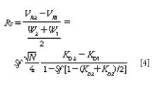
The quality of a chromatographic separation is measured by the chromatographic resolution factor, Rs, that is essentially the retention volume difference between two adjacent peaks divided by the average peak width at the base, W. The Snyder equation is used in HPLC and gas chromatography (GC) techniques where the stationary phase volume is constant. In CCC, the resolution, Rs, critically depends on the volume of stationary phase, VS; hence, the resolution depends on the stationary phase retention ratio, Sf . The CCC resolution is expressed by equation 4:

Table I: Calculated solute retention volumes, retention times, and resolution factors for six samples (AâF) separated using four different sizes of countercurrent chromatography (CCC) columns
where N is the average peak efficiency expressed in the theoretical plate number (5). Table I lists the Rs value for the hypothetical separation of six solutes in different CCC columns working with the same liquid system. The Sf, N, and F data listed for the small-volume (30 mL) and semipreparative (250-mL) columns were observed experimentally. Those for the 1-L and 20-L columns are theoretical values. If the relative amount of stationary phase (Sf) and plate efficiency (N) are the same in two columns of different volumes, the solute retention volumes will be different but the resolution factors will be the same. This is the case for the 1-L scale and the 20-L CCC columns in Table I.
Equation 4 shows the direct relationship between Sf and Rs; however, Sf also appears in the solute-depending fraction, so that it is not a linear relationship. Figure 1 illustrates the changes observed on the resolution factor, Rs, when the amount of stationary phase contained in the CCC column changes for different solutes. Such Sf changes are experimentally observed as column bleeding. The mobile phase carries over small amounts of liquid stationary phase, producing an Sf parameter that decreases with time (1,5). In Figure 1, the selectivity factor (ratio of the distribution ratios K2/K1) is constant, equal to 1.5. As is most often experimentally observed, the peak efficiency decreased when the solute retention increased: Well-retained compounds are broader than less strongly retained compounds (3). Polar or low KD solutes (KD < 1) are associated with concave Rs vs. Sf curves; less polar or higher KD solutes (KD > 1) have convex Rs vs. Sf curves (Figure 1). In all cases, the resolution factor, Rs, increases as the volume of stationary phase contained in the CCC columns increases. Obviously, there is no separation (Rs = 0) when there is no stationary phase retained in the CCC column (Sf = 0).
It is always observed that increased mobile-phase flow rates are associated with decreased liquid stationary phase retention volumes (lower Sf values) when the centrifugal field is constant. Consequently, a good CCC column must be able to generate a strong centrifugal field to retain the largest possible liquid stationary phase volume, working as quickly and efficiently as possible.
Experimental
Hydrodynamic and Hydrostatic CCC Columns
There are two main types of CCC columns. Hydrodynamic CCC columns contains continuous open tubing coiled on bobbins rotating with a planetary motion (without any rotary seal). Hydrostatic CCC columns contain small interconnected chambers that retain the liquid stationary phase when placed in a centrifuge rotor with two rotary seals at both ends of the rotor. These two types of CCC columns have been described in detail in the literature (1–3). To summarize, hydrodynamic columns have very good efficiency, producing sharp, well-separated peaks when the liquid system used is correctly retained. Hydrostatic columns have a lower efficiency but are better able to retain any liquid stationary phase. The retention equation and chromatographic process are the same for both kinds of CCC columns.
Small CCC columns are desirable because they allow for fast purification optimization and for significant reduction in the amount of solvent used (4). Small-volume hydrodynamic CCC columns have been commercialized and found to be very useful. However, they have not been able to work with flow rates much faster than 1.5 mL/min because of serious bleeding of liquid stationary phase at higher flow rates. A CCC hydrostatic column with a 50-mL rotor also has been commercialized, but this column can only work at limited pressure (<50 bar or 700 psi) and at rotor rotation speeds not exceeding 2000 rpm because of rotary seal problems (6).
Small Hydrostatic CCC Rotor
For the work described here, stainless steel disks were engraved with 64 pairs of cells per disk, for a total cell volume of 2 mL per disk. The interconnecting ducts had a volume of 0.8 mL per disk. Thus, the total liquid volume per disk is calculated to be 2.8 mL. A total of 13 disks were stacked together to make a hydrostatic rotor with a calculated rotor volume of 2.8 × 13 = 36.4 mL, with 832 pairs of cells. Two similar rotors were manufactured, one mounted in a fast centrifugal partition chromatography (FCPC) case (Kromaton Rousselet-Robatel) and the other mounted in a sealed, dedicated case. The experimental volume of a full CCC setup including pump, injection valve (1-mL loop), CCC column, and detector had to be measured by injecting acetone in the system filled with pure water. For the rotor mounted in the FCPC case, the measured acetone retention volume was 38 mL, or close to 2 mL greater than the calculated rotor volume of 36.4 mL. For the second rotor, mounted in a sealed case, the measured acetone volume was 32 mL. These experimental volumes make sense because the injection loop and connecting tubing volumes were both included in the experimental acetone determination.
In CCC, the chromatographic process can take place only when the two liquid phases are in contact. In the hydrostatic design, the connecting ducts contain only the mobile phase. The total cell volume is only 25.8 mL with 832 (64 × 13) pairs of cells in which chromatographic exchanges can occur. Considering the measured column volume of 38 mL (for the rotor in the FCPC case), 12.2 mL (38 – 25.8) of the volume is contained in the interconnecting ducts within the rotor and in the extrarotor tubing, all of which contain only mobile phase (which means that no chromatographic exchanges occur there). This means that the 38-mL hydrostatic column can retain a maximum of 25.8 mL of stationary phase, so its maximum Sf value will be 67.9% (25.8/38), regardless of the biphasic liquid system used.
The second, very similar rotor was mounted in a different prototype case with reduced and optimized extrarotor volume. Its volume characteristics were very similar, with a maximum theoretical Sf of 80.6% (25.8/32).
Two Cases for the Same Rotor
The rotor was first tested in an FCPC case including a central axis belt connected to a motor with adjustable rotation speed. New rotary seals able to withstand pressures as high as 80 bar (1100 psi) and rotor speeds as high as 3000 rpm were used. This FCPC case can work with rotors with volumes of 36–500 mL. A prototype model, R2D2 (Rousselet Robatel Decisive Design), was also developed, with the same rotor mounted directly on the motor axis with the improved new rotary seals and enclosed in a relatively small sealed case with a single valve to select the direction of the entering fluid (ascending or descending). The column volume of the prototype model was experimentally measured (by injecting acetone in the water-filled column) as 32 mL.
The experimental results obtained with these two small-volume hydrostatic CCC columns (the FCPC model mounted with the 38-mL rotor and the prototype) were very similar when used under identical experimental conditions of liquid system, sample, rotor rotation, and flow rate.
Results
This work describes the use of these small CCC columns designed to test potential biphasic liquid systems. No original separation will be presented. Rather, previously published separations performed with a variety of biphasic liquid systems will be tested on the small columns to evaluate the capabilities of the small columns. The focus will be on comparing liquid stationary phase retention (Sf parameter), solvent volume needed to complete the purification, and experiment duration.
Biphasic Liquid System of 10:9:1 (v/v) Heptane–Methanol–Water
The 10:9:1 (v/v) heptane–methanol–water biphasic liquid system is very convenient to evaluate a CCC column because its upper organic phase is practically pure heptane: It is 99.9% heptane, with traces of methanol (7). The lower phase of the system is 85% methanol, 10% water, and 5% heptane (v/v.) With a heptane mobile phase, it is possible to add pure heptane to the system continuously without any liquid–liquid disturbance.
Toluene and butylbenzene are two members of the alkylbenzene homologue family whose partitioning in the heptane–methanol–water biphasic liquid system was studied extensively (8). They were used as test solutes for the small CCC columns. Figure 2 shows the chromatograms obtained at different rotor rotations with heptane as the mobile phase in the ascending mode at 5 mL/min with a methanol–water stationary phase. At the 5-mL/min flow rate, a column volume is swept in 7 min. The toluene–butylbenzene separation is completed in <5 min or five times faster than the published separation (8). However, when the rotor rotation speed is lower than 2000 rpm, the resolution factor drops and the two peaks overlap.
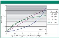
Figure 1: Changes in the resolution factor, Rs, between two peaks with selectivity α = 1.5 and first peak distribution ratio K1 as listed on the right, with efficiency N, as a function of the stationary phase volume (factor Sf = VS/VC) contained in the CCC column. A straight line is obtained for the compounds with K1 = 0.8 and K2 = 1.2 (selectivity 1.2/0.8 = 1.5) forming (K1 + K2)/2 = 1; see resolution equation 4.
Figure 3 shows the resolution factor between toluene and butylbenzene and the stationary phase retention factor, Sf, in percentage of column volume, plotted versus the rotor rotation speed. As the centrifugal field decreases (as the rotor rotation speed decreases), the resolution factor drops. This is mainly a result of the loss of aqueous stationary phase, seen in the decreasing Sf value. It is also a result of lower peak efficiencies (equation 4). The butylbenzene peak efficiency passes 650 theoretical plates at 3000 rpm and then decreases almost linearly down to 400 plates at 500 rpm. The toluene peak efficiency shows the same trend, decreasing from 450 plates at 3000 rpm to 100 plates at 500 rpm. These results were previously observed with a different hydrostatic CCC column (9).
Octanol–Water Partition Coefficient Determination
When the biphasic liquid system is made of the two solvents octanol and water, the compound retention volumes give directly, as KD values, the respective octanol–water distribution ratios, commonly called partition coefficients,Po/w. Equation 1 shows that there is no assumption or extrapolation in this direct measurement. The problem is the measurement range: A large Po/w value will need excessive volumes of aqueous phase or the stationary octanol phase volume must be as reduced as much as possible. Also, highly retained compounds may be difficult to detect because they are very diluted in the aqueous mobile phase (1,5,7).
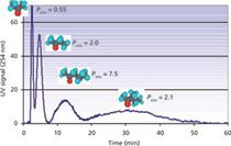
A simple mixture of four ketones was used to demonstrate the capability of the 38-mL hydrostatic CCC column. The column was filled with octanol saturated by water. The water content in the upper octanol phase was 4.1% w/w (34 g/L), or 1.9 M at 20 °C. The rotor was rotated at 1800 rpm and the aqueous mobile phase saturated in octanol (octanol content is only 0.054% w/w [0.54 g/L] or 4.1 mM at 20 °C) was pumped at 12 mL/min in the descending direction (10). The octanol stationary phase retention ratio in these experimental conditions was 43.4% (Voct = 16.5 mL). A 1-mL volume of sample made by mixing 1 mL of pure acetone, 1.5 mL of methyl ethyl ketone, 1.5 mL of methyl propyl ketone, and 3 mL of methyl isobutyl ketone was injected, producing the chromatogram shown in Figure 4 in less than 1 h. The respective ketone retention volumes could be determined using equation 1 with the corresponding KD distribution ratios that are actually the ketone Po/w coefficients, which were in excellent agreement with the literature values (10).
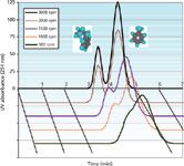
Figure 2: Chromatograms of 0.2 mg butylbenzene and 0.4 mg toluene (1 mL injected) obtained using hydrostatic CCC columns (FCPC, 38 mL) rotating at five different speeds (rpm). Liquid stationary phase: aqueous lower phase of a heptane-methanol-water system (10/9/1 v/v); mobile phase: heptane upper phase at 5 mL/min in the ascending direction. See Figure 3 for resolution factors, Rs, and stationary phase retention ratios, Sf.
The benefits of using a small-volume CCC column are obvious in this case. The methyl propyl ketone and methyl isobutyl ketone Po/w coefficients are 7.5 and 21, respectively, needing 145 mL and 370 mL and 12 and 31 min at 12 mL/min (Figure 4) for peak maxima and close to 240 mL and 700 mL or 20 min to 1 h at 12 mL/min for complete elution. If the semipreparative 250-mL CCC column (Table I) was used with the same octanol stationary phase retention (Sf = 43%, Voct = 108 mL), the respective methyl phenyl ketone and methyl isobutyl ketone retention volumes would be 950 mL and 2410 mL, needing a prohibitively large 4 L of aqueous phase for complete elution, and the separation would take hours.
Aqueous Two-Phase System of PEG 1000–K2HPO4–H2O
Aqueous two-phase systems (ATPS) are composed of two immiscible aqueous phases. These biphasic liquid systems are very interesting in liquid–liquid extraction and CCC, and form the most polar possible systems. Proteins and biological material can be partitioned in ATPS (11). However, it is difficult to retain a polar ATPS stationary phase in a CCC column because of the relatively high viscosity of the phases and the very low interfacial tension between the two aqueous phases. Hydrostatic CCC columns were shown to be superior to the hydrodynamic ones for ATPS phase retention (11).
A mixture of lyzozyme (129 amino acid residues, 14.7 kDa) from chicken egg white and myoglobin (153 amino acid residues, 18.7 kDa) from bovine meat was used as a test mixture in several published works with an aqueous two-phase system of 14:14:72 (w/w) polyethylene glycol (PEG) 1000–K2HPO4–water (w/w) (3,11,12). The prototype 32-mL hydrostatic CCC column was selected to work with this test mixture and ATPS. Figure 5 gathers the chromatograms obtained at three different phosphate-rich aqueous lower mobile phase flow rates in the descending mode with the PEG-rich aqueous stationary upper phase. Table II lists the corresponding chromatographic data.
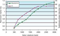
Figure 3: Toluene/butylbenzene resolution factor and Sf ratio corresponding to the Figure 2 chromatograms. Columns: hydrostatic CCC columns (FCPC, 38 mL); liquid stationary phase: aqueous phase (85% methanolâ10% waterâ5% heptane, v/v); mobile phase: heptane at 5 mL/min in the ascending direction.
The first observation is the remarkable retention of the PEG-rich aqueous phase by the hydrostatic column, producing baseline separation of the two proteins. Comparing this separation with previously published ones, the full myoglobin–lyzozyme protein separation obtained at 6 mL/min in <12 min is probably the fastest ever obtained (3, 11,12). It is important to point out that the chromatograms in Figure 5 were all obtained with on-line UV detection at 220 nm. The aqueous stationary phase bleed was almost nil at 2 mL/min and 4 mL/min; it was estimated to be 0.1 mL/min at 6 mL/min, producing the noisy chromatogram of Figure 5. Table II lists the Sf stationary phase retention data, which confirm one more time that Sf is critically dependent on the mobile phase flow rate.
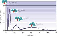
Figure 4: Direct measurement of octanolâwater partition coefficient, Po/w, of four ketones with an injection volume of 1 mL. Peaks: acetone (115 mg), methyl ethyl ketone (170 mg), methyl propyl ketone (170 mg), and methyl isobutyl ketone (345 mg). Column: hydrostatic CCC column (FCPC, 38 mL) rotating at 1800 rpm; liquid stationary phase: 16.5 mL octanol water saturated, Sf = 43%; mobile phase: aqueous lower phase at 12 mL/min in the descending direction; pressure: 42 bar (600 psi).
The lower right quadrant of Figure 5 shows the three previous chromatograms redrawn with a reduced VR/VC dimensionless abscissa (9). This representation is a very good illustration of the unique CCC resolution equation (equation 4). Faster flow rates actually produced narrower peaks (higher efficiency). The higher plate number (N) values did not improve the resolution factor (Rs) because in CCC, the stationary phase retention ratio, Sf, has more weight than N (equation 4). The decrease in resolution evidenced by the combined chromatograms in the lower right section of Figure 5 is a consequence of the lower stationary phase volume retained in the CCC column (Table II).
Conclusion
Countercurrent chromatography is to liquid–liquid extraction what HPLC is to solid-phase extraction. Extraction is the single process that is automatically repeated a number of times in the chromatographic column. The support-free liquid stationary phase is the heart of the CCC preparative technique (1). It is responsible for both the advantages and problems associated with CCC. The absolute requirement for purifying any compound by CCC is that some liquid stationary phase must be retained inside the column.
The small-volume hydrostatic columns discussed here achieved a very decent chromatographic efficiency associated to a remarkable potential to retain liquid stationary phases including those of the most difficult systems: the polar aqueous two-phase liquid systems. The selected published separations were able to be performed five to 10 times faster by using these small-volume hydrostatic columns. The small volume of the columns does not permit the purification of large amounts of material. However, it allows for rapid elution of solutes with an elevated distribution ratio. It will be very useful for accurate determination of distribution ratios, especially octanol–water partition coefficients.
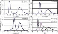
Figure 5: Separation of myoglobin (first peak) and lyzozyme (second peak) using an aqueous two-phase system on a 32-mL hydrostatic CCC column (prototype R2D2) at 2000 rpm at different flow rates of the lower phosphate-rich aqueous phase in the descending mode. The lower right part of the figure shows the same three chromatograms in a relative volume scale (VR/VC). Injection volume: 1 mL; sample: lyzozyme 8.3 g/L, myoglobin 4.3 g/L.
A chemist's expertise is still required to determine which biphasic liquid system will be appropriate for a particular purification in CCC. However, the use of a small-volume hydrostatic CCC column will be helpful for quickly testing which biphasic liquid system is optimal for a given purification. After an acceptable chromatogram is obtained, the experimental conditions can be geometrically scaled up on a larger CCC column, either hydrodynamic, if it can retain the selected liquid stationary phase, or hydrostatic (13). Given that determining the appropriate biphasic liquid system is the bottleneck in setting up a CCC purification, this approach will be a significant contribution to the development and adoption of the underestimated CCC technique. Purification laboratories not using CCC could also use this approach to make quick tests, allowing them to gain knowledge about the purification power of this poorly known technique.

Table II: Chromatographic data corresponding to Figure 5
References
(1) A. Berthod, "Countercurrent Chromatography: The Support-Free Liquid Stationary Phase," in Comprehensive Analytical Chemistry, Vol. XXXVIII, B. Barceló, Ed. (Elsevier, Amsterdam, 2002).
(2) A. Marston and K. Hostettmann, LCGC Europe 21(4), 218–222 (2008).
(3) I.J. Garrard, D. Fisher, and I.A. Sutherland, LCGC North America 26(5), 2–7 (2008).
(4) A. Berthod, S. Ignatova, and I.A. Sutherland, J. Chromatogr. A 1216, 4169–4175 (2009).
(5) A. Berthod, Adv. Chromatogr. 47, 323–352 (2009).
(6) A. Maurya, S. Gupta, and S. Kumar, Sep. Sci. Technol. 46, 1195–1199 (2011).
(7) W.D. Conway, Countercurrent Chromatography, Apparatus, Theory and Applications (VCH Publishers, Weinheim, Germany, 1990).
(8) A. Berthod and M. Bully, Anal. Chem. 63, 2508–2512 (1991).
(9) L. Marchal, A. Foucault, G. Patissier, J.M. Rosant, and J. Legrand, J. Chromatogr. A 869, 339–352 (2000).
(10) M.J. Ruiz-Angel, S. Carda-Broch, A. Levet, and A. Berthod, J. Chromatogr. A 1218, 6044–6052 (2011).
(11) I.A. Sutherland, Curr. Opin. Drug Disc. Devel. 10, 540–549 (2007).
(13) I.A. Sutherland, G. Audo, E. Bourton, F. Couillard, D. Fisher, I. Garrard, P. Hewitson, and O. Intes, J. Chromatogr. A 1190, 57–62 (2008).
(14) A. Peng, R. Li, J. Hu, L. Chen, X. Zhao, H. Luo, H. Ye, Y. Yuan, and Y. Wei, J. Chromatogr. A 1200, 129–135 (2008).
Karine Faure is a tenured research associate of the French National Center for Scientific Research (CNRS) at the Analytical Science Institute of the University of Lyon (CNRS UMR 5280), in Villeurbanne, France.
Nazim Mekaoui is a graduate student supported by the French Department of Research and Industry at the Analytical Science Institute of the University of Lyon.
Alain Berthod is a professeur agrégé and a research director at the CNRS at the Analytical Science Institute of the University of Lyon.
Jeremy Meucci is a principal scientist at Kromaton-Rousselet-Robatel at Annonay, France. Direct correspondence to: berthod@univ-lyon1.fr.

University of Rouen-Normandy Scientists Explore Eco-Friendly Sampling Approach for GC-HRMS
April 17th 2025Root exudates—substances secreted by living plant roots—are challenging to sample, as they are typically extracted using artificial devices and can vary widely in both quantity and composition across plant species.
Thermodynamic Insights into Organic Solvent Extraction for Chemical Analysis of Medical Devices
April 16th 2025A new study, published by a researcher from Chemical Characterization Solutions in Minnesota, explored a new approach for sample preparation for the chemical characterization of medical devices.


