Retention Time Changes
LCGC North America
What happens when the same method gives different retention times on different instruments?
What happens when the same method gives different retention times on different instruments?
This month's installment comes from a question submitted by a regular reader (Justin Chow), which developed into a joint troubleshooting project. Before we get into the question, let me remind and encourage you to send me questions about problems you are having (see contact information at the end of this article). I'm happy to give you my input, and who knows . . . your problem may form the basis of one of the "LC Troubleshooting" discussions, as is the case this month.
The Problem
The problem has to do with differences in retention time that were observed when the same method was run on three different brands of liquid chromatographs, which we'll refer to as system A, system B, and system C. As often is the case, the method was one that was transferred from another laboratory, so complete details about the logic behind the method are not available. The method comprises an isocratic segment for 62 min at 95% A and 5% B followed by a 23-min gradient segment of 5–95% B. Finally, the mobile phase is stepped back to the initial conditions and allowed to equilibrate for the next injection. Both mobile-phase A and B contain buffer and organic solvent, with more organic in B. Note that both buffers A and B are prepared using volumetric glassware to eliminate variations from graduated cylinders. The column is a 150 mm × 3.0 mm, 2.6-µm particle diameter (dp), C18 column operated at 0.6 mL/min. As part of the method transfer process, the same method was used to compare the chromatography on the three LC systems, all of which are four-solvent, low-pressure mixing systems. The dwell volumes for all systems are approximately the same. The main peak gave different retention times on each system: 49 min (system A), 55 min (system B), and 61 min (system C). Although the variability between systems A and B (49 vs. 55 min) is within the range observed by workers in other laboratories, the retention time for system C (61 min) is excessively long. Furthermore, later-eluted peaks that normally appeared in the isocratic segment now came off the column during the gradient segment and were not adequately separated. The problem, of course, is why are the retention differences observed, how can the problem source be verified, and how can it be fixed? This problem also serves to illustrate how we can use some simple calculations to evaluate the probable cause of the problem.
Undesirable Conditions
It is a bit unusual to have such a long isocratic portion in the method, but it works for the present application and is part of a validated method that is best not modified, if possible. However, it should be noted that the peak properties will suffer from such large retention times. The column plate number, N, is calculated as

where t R and w are the retention time and baseline peak width, respectively. We can estimate the plate number for a column when real samples are run as

where L is the column length (in millimeters) and d p is the particle diameter (in micrometers). So for our 150 mm × 3.0 mm, 2.6-µm d p column, N ≈ 17,000. Solving equation 1 for w and using N = 17,000 and t R = 50, we can estimate w = 1.5 min or 0.9 mL at 0.6 mL/min flow rate. A peak eluted at 10 min would have one-fifth this width and consequently five times the height — not a small change in response. Therefore, the long retention time means that method sensitivity (peak height) may be poor.
Another check we can make on the quality of the chromatography is to consider the retention factor, k. For the best isocratic methods, we like 2 ≤ k ≤ 10, but in some cases all the peaks won't fit within this range so we accept 1 ≤ k ≤ 20. When the retention range exceeds this, a gradient method usually is preferred. Recall that k is calculated as

where t 0 is the column dead time. The column volume can be estimated as

where V M is the column volume (in milliliters) and d c is the column internal diameter (in millimeters). Our 150 mm × 3.0 mm column will have a volume of ≈ 0.675 mL, and at a flow rate of 0.6 mL/min, t0 ≈ 1.125 min. Thus, for tR = 50, we get k = (50 – 1.125)/1.125 = 43; this is much larger than the maximum desired k ≈ 20, so a gradient method probably would be a better choice. But we have to work with the current method to separate some very closely related compounds, so let's try how to figure out what's wrong.
The Effect of Mobile-Phase Errors
Because the same method is used on all three instruments, one possible cause of the problem is that the systems are not producing the same blend of mobile phase. We can estimate how much the mobile phase will change retention by taking advantage of the relationship between mobile-phase strength and retention:

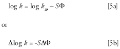
where k w is the retention time in 100% water and Φ is the %B as a decimal (Φ = 0.01 = 1% B). S is a constant for a given compound and can be estimated as S ≈ 0.25.MW0.5 , where MW is the molecular weight. If we assume a 400 Da compound, we can use S = 5 for our present calculations. Let's consider two cases, first the 49 min (k ≈ 42.6, system A) vs. 55 min (k ≈ 47.9, system B) "normal" variation and the unexpected 52 min (k ≈ 45.2, average for systems A and B) vs. 61 min (k ≈ 53.2, system C) change.
For the first case, log 42.6 = 1.629 and log 47.9 = 1.680, so Δ log k = (1.680 – 1.629) = 0.05 (note that I've rounded the numbers for convenience, so if you try to reproduce these calculations, don't round during the process). Divide by S and we get ΔΦ = 0.010. This suggests that systems A and B differ by 1% B, which is marginally within the normal calibration range of ±1% B (see discussion below). For the second case, log 45.2 = 1.655 and log 53.2 = 1.726, so Δ log k = (1.726 – 1.655) = 0.070, so ΔΦ = 0.070/5 or 1.4% B. In other words, we can account for the difference between the longest retention time (61 min, system C) and the average retention from systems A and B (52 min) by a difference of 0.4% B in the mobile-phase composition. This small variation is probably within normal error, but it is possible that system C may be out of calibration. Next, we need to check the calibration of the mixing system for system C.
Checking Mixer Calibration
A check of the calibration of the mobile-phase mixing system is part of system performance qualification (1), which we recommend performing every 6–12 months on each LC system in your laboratory. The mixing can be tested quite easily with the gradient step-test. This test is performed as follows:
- Remove the column and replace it with a piece of capillary tubing; ≈1 m of 0.125-mm (0.005-in.) i.d. tubing, such as the red PEEK (polyetheretherketone) tubing, which works well. This has an insignificant volume (≈12 µL) and generates enough back pressure that the pump works well.
- Replace the A-solvent with water and the B-solvent with water containing 0.1% acetone. If you want to check the C- and D-solvents, put the C-inlet tubing in the A reservoir and D in B.
- Set the flow rate to 2 mL/min and the UV detector wavelength to 265 nm, where acetone absorbs strongly.
- Program and run a series of isocratic steps, 4 min each. Steps of 0, 10, 20, 30, 40, 50, 60, 70, 80, 90, and 100% B work well.
The test should be run for each LC system and each combination of solvents that might be used for a method. Currently we're only concerned about the A- and B-solvents, but C and D should be tested as well.
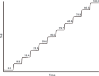
The results for a test of system C are shown in Figure 1. Measure the difference between the 0% and 100% steps and use this to determine the height of each intermediate step. In Figure 1, you can see that most of the steps vary a little from the target values (even 10% increments), but the worst deviation is the 20% step, which comes out 0.6% low at 19.4%. Pump specifications typically are ±0.5–1%, so ±1% is a reasonable acceptance limit for this test. Everything looks OK for system C from the step test.

Figure 1
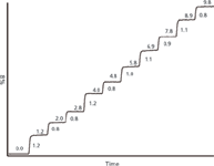
For cases in which subtle solvent proportioning errors are suspected, such as in the present example, it may make sense to make finer step sizes around the suspect region — 0–10% in 1% steps in this case. The results are shown in Figure 2. The absolute %B obtained is shown above each step and the actual step size shown to the right of each step. Here, as in the 10% steps of Figure 1, the absolute value of each of the steps is within 1% of the set-point, so the instrument passes specifications in the 0–10% region (note that from Figure 1, we know that this is 0–9.8%; Figure 2 reflects this). Furthermore, the anticipated 0.4% deviation at 5% B, determined from the earlier calculations, is not observed. The 5% step in Figure 2 measures 4.8%, only 0.2% from the ideal. However, the step sizes in Figure 2 are a bit odd. Note in Figure 1 that all the steps except 0 and 100% are low by 0.1–0.6%, with a general trend of larger deviations at lower %B-values. But in Figure 2, the step 1–2 and 2–3 intervals are 0.8% and the step 0–1 and 3–4 intervals are 1.2%. This inconsistency in step sizes was the only difference that could be linked to system C, so the proportioning valve assembly was replaced as a precautionary measure. System C with the new proportioning valve gave a retention time of 57.7 min for the main peak, which was still a bit longer than the other laboratories were finding. However, the poorly separated peaks that were eluted during the early part of the gradient segment now are eluted in the isocratic separation and have adequate separation. At this point, the problem was considered solved and the method was put into routine use on system C.

Figure 2
A Simpler Solution
The above problem highlights the challenge of obtaining sufficient precision and accuracy with on-line mixing to obtain consistent retention times for strongly retained peaks. A much simpler solution to the problem of instrument-to-instrument differences would be to use hand-mixed mobile phase for the isocratic portion. That is, hand mix a mobile phase of 95% A and 5% B and put this in the A-reservoir. Separately, hand mix a mobile phase of 5% A and 95% B and put this in the B-reservoir. Now, run the program for 62 min at 0% reservoir-B and then program a gradient to 100% reservoir-B in 23 min. This suggestion was tested and the retention time of the main peak came out much later. A further minor adjustment of the initial mobile-phase composition (by adding a little more of the B-solvent for the initial isocratic hold) should bring the retention time back to the target value.
Summary
We've looked at a problem of instrument-to-instrument differences in retention time and speculated that the most likely cause was a difference in mobile-phase proportioning between the systems. We used simple back-of-the-envelope calculations based on normal chromatographic behavior to estimate the magnitude of mobile-phase composition errors. After we knew what to look for in terms of the scale of the problem, we used the gradient step-test as a means of checking instrument calibration. Although the test results showed compositional differences that would most likely be unimportant for methods with shorter retention times, a replacement of the mobile-phase proportioning valve corrected the problem. If you would like to see more examples of problems related to proportioning errors, consult reference 3.
Justin Chow is an associate scientist at Gilead Sciences, Inc., in Foster City, California. He specializes in HPLC method development, separation of closely related compounds, impurity elucidation using LC–MS, and instrument troubleshooting.

Justin Chow
John W. Dolan "LC Troubleshooting" Editor John Dolan has been writing "LC Troubleshooting" for LCGC for more than 25 years. One of the industry's most respected professionals, John is currently the Vice President of and a principal instructor for LC Resources, Walnut Creek, California. He is also a member of LCGC's editorial advisory board. Direct correspondence about this column via e-mail to John.Dolan@LCResources.com.

John W. Dolan
References
(1) G. Hall and J.W. Dolan, LCGC 20(9), 842–848 (2002).
(2) J.J. Gilroy and J.W. Dolan, LCGC 22(10), 982–988 (2004).
(3) L.R. Snyder and J.W. Dolan, High-Performance Gradient Elution (Wiley-Interscience, Hoboken, New Jersey, 2007), section 5.5.3.

Extracting Estrogenic Hormones Using Rotating Disk and Modified Clays
April 14th 2025University of Caldas and University of Chile researchers extracted estrogenic hormones from wastewater samples using rotating disk sorption extraction. After extraction, the concentrated analytes were measured using liquid chromatography coupled with photodiode array detection (HPLC-PDA).
Polysorbate Quantification and Degradation Analysis via LC and Charged Aerosol Detection
April 9th 2025Scientists from ThermoFisher Scientific published a review article in the Journal of Chromatography A that provided an overview of HPLC analysis using charged aerosol detection can help with polysorbate quantification.
Removing Double-Stranded RNA Impurities Using Chromatography
April 8th 2025Researchers from Agency for Science, Technology and Research in Singapore recently published a review article exploring how chromatography can be used to remove double-stranded RNA impurities during mRNA therapeutics production.


