Mobile-Phase Degassing: What, Why, and How
Why should you be concerned about mobile-phase degassing - it's all done automatically, isn't it?
Why should you be concerned about mobile-phase degassing — it's all done automatically, isn't it?
Degassing of the mobile phase in liquid chromatography (LC) applications is a topic that is seldom talked about today. However, this was not the case in the past. For the first 30 years or so of LC use, problems related to mobile-phase outgassing were some of the most common problems encountered in routine use. This was true in user surveys conducted by LCGC as well as by my informal polls based on readers' questions and direct interactions with users. Over the past 15–20 years, on-line degassers have moved from a novelty device to a standard part of most LC systems. As a result, I suspect that many users have never encountered problems related to degassing. I dropped an in-depth discussion of degassing from my popular LC troubleshooting class, but in a recent class the topic came up again. Although in-line degassing helps us avoid most solvent out-gassing problems, it does not solve all problems related to dissolved air in the mobile phase. In this month's instalment of "LC Troubleshooting" I would like to review what degassing is all about. What is it? Why do we need it? How is it accomplished? Are there times when we should be especially watchful for problems related to it?
Why Degas the Mobile Phase?
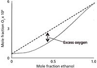
When solvents are in contact with the atmosphere, air gradually dissolves into the solvent. Air, of course, is primarily nitrogen and oxygen. In reversed-phase LC, the most common solvents are water or buffer as the A-solvent and acetonitrile or methanol as the B-solvent. When the aqueous and organic solvents are mixed, they each contribute to the total dissolved air content of the mixture. This is illustrated by the dashed line in Figure 1 for the solubility of oxygen in mixtures of water and ethanol (which behaves in a similar manner for oxygen and nitrogen with methanol and acetonitrile for the present discussion). Whether we are making isocratic (constant %B) mixtures or gradients, the amount of gas in solution is in proportion to the respective solvent volumes. The problem with this situation is that the solubility of air in the mixture is less than that of individual components. This is shown as the solid curve in Figure 1. When such a situation exists, the solution is supersaturated with air, generating an unstable condition in which air will bubble out, or outgas, from the solution.

Figure 1: Solubility of oxygen in ethanol (dashed line); saturation concentration of oxygen in the mixture (solid line). See text for details. Adapted from reference 1.
If mobile-phase outgassing occurs within the LC system, the most common problem areas are the pumps and detector. At the extreme, air in the pump will cause the pump to stop delivering mobile phase to the column. If only an occasional bubble is present, the flow rate will be erratic, causing retention time problems. Air in an optical detector, such as an ultraviolet (UV), fluorescence, or refractive index detector, will scatter light passing through the flow cell, causing noise spikes in the chromatogram or an off-scale signal. These problems can be eliminated if the air is removed from the mobile phase.
Early Solutions
The data of Figure 1 suggest that to avoid mobile-phase outgassing we do not have to remove all the dissolved gas from solution, but only reduce the total amount of dissolved gas so that a plot for the resulting mixture would result in a line falling below the solid line in Figure 1 (1). If half of the dissolved gas is removed, we should be safe. One simple way to do this is to use a vacuum to degas the solvents. This can be done easily by placing the solvent in a vacuum flask and pulling a partial vacuum with a water aspirator or mechanical pump of similar capacity. To help facilitate the process, a stir bar or a few (clean!) boiling stones can be added to the flask. Although I don't have quantitative data on this, many workers find that sonicating the solution while vacuum degassing seems to be more effective than vacuum alone. In any event, a few minutes of vacuum degassing will remove about 60–70% of the dissolved gas (2). Sonication alone will only remove 20–25% of the gas (2), which is insufficient to avoid outgassing with most LC systems. For some LC systems, the amount of vacuum applied while filtering the mobile phase may remove enough gas to avoid problems. The most effective way to degas the solvents is to bubble helium through the mobile phase by sparging for a few minutes, which removes approximately 80% of the dissolved air (2). It seems contradictory to use a gas to degas a solution, but the solubility characteristics of helium in the mobile phase are such that outgassing is not a problem. Helium sparging was widely used for degassing, and although it is used less today because of the ease of in-line vacuum degassing and decreased availability of helium, it is still the most effective degassing technique.
Until the late 1970s, all LC systems were run with either premixed mobile phases in the isocratic mode or used high-pressure mixing to generate a gradient by mixing the mobile-phase components after the pumps. With these systems, the premixed mobile phase was degassed before use or the individual solvents were degassed for gradient applications. On-line mixing of isocratic mobile phases was also possible if the solvents were degassed first. The advantage of high-pressure mixing is that the pumps only pump degassed solvents or mobile-phase mixtures, and because the solvents were mixed under pressure, any bubbles that might otherwise form at atmospheric pressure would stay in solution because of the elevated pressure of the system. Often, care had to be taken to provide a small back pressure (for example, 50 psi) on the outlet of the detector to keep the mobile phase from outgassing in the detector cell.
In the late 1970s, Spectra-Physics (now a part of Thermo Fisher Scientific) introduced an LC system that incorporated low-pressure mixing. Solvents were blended in a proportioning manifold before they reached the pump, a technique that is used in low-pressure mixing systems offered by most LC manufacturers today. When low-pressure mixing is used, the solvents are mixed at atmospheric pressure (or sometimes a bit below atmospheric pressure), so outgassing of the mobile phase is a huge problem. The Spectra-Physics system included a built-in helium sparging system to degas the solvents before mixing, so outgassing was avoided. Although Spectra-Physics had a patent on helium sparging (3), which discouraged other manufacturers from offering the same technology, it was hard to prevent individual users from constructing their own helium sparging apparatus for personal use, so the technique became popular.
In-Line Degasser
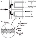
Although in-line degassing was patented in 1984 (4), it was not often used in LC systems until the late 1990s. More recently, in-line degassing has become the most common degassing technique — a standard component of most new LC systems. The function of the in-line degasser is illustrated in Figure 2. The degasser comprises a gas-permeable tube or membrane, through which the mobile phase passes, and a vacuum chamber as in Figure 2(a). The membrane is similar to the semipermeable membrane used in rain jackets, which liquid water is not able to penetrate, but water vapour does pass through. When vacuum is applied on the outside of the membrane (Figure 2[b]), dissolved gas passes through the pores in the membrane and the liquid mobile phase stays inside. When the proper combination of membrane porosity, vacuum, and residence time is used, the in-line degasser removes enough dissolved gas to avoid outgassing so that the LC pump will operate reliably.

Figure 2: Schematic of in-line vacuum degasser: (a) Flow path; (b) expanded section to illustrate gas passing through semipermeable membrane. See text for discussion.
In-line degassers are quite reliable, and will operate for months or years with little or no maintenance. It is a good practice to avoid storage of the degasser with buffer or water in the tubing, because microbial growth can occur, and the pores can become blocked or general contamination can occur. A small amount of biological contamination may be removed by flushing all the mobile-phase pathways with 30% phosphoric acid and then rinsing with water (check the system maintenance manual for specific instructions and precautions). In some cases, the membranes may need to be replaced when contaminated, an expensive event, so it is best to avoid it by removing aqueous phases when not in use. Other failures can occur if the vacuum pump fails or the tubing between the vacuum manifold and the pump or pump and waste are damaged, blocked, or come loose.
Because in-line degasser use is almost universal, and in general requires little or no maintenance, many users are not aware of problems related to bubbles in the mobile phase. Although in-line degassers are effective in reducing the total gas burden of the mobile phase to acceptable levels, dissolved air still remains in the mobile phase. For some applications, this residual air can cause problems, as is noted below.
Problems with Dissolved Oxygen
For LC applications using UV detection at wavelengths greater than 200 nm, mass spectrometry (MS) detection, and many other LC detectors, a little residual dissolved gas in the mobile phase is not a problem. As mentioned above, for detectors that rely on passing mobile phase through an optical path, such as refractive index or UV detectors, as long as air bubbles are not present, problems are rare. A slight back pressure on the flow cell, such as that created by using a capillary tube for a waste line or installing a back-pressure regulator after the cell, will be sufficient to avoid outgassing in the flow cell. In other cases, dissolved oxygen, even at low concentrations, may compromise detection.
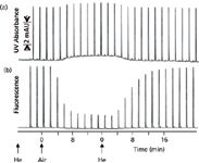
An example of compromised fluorescence detection for naphthalene is shown in Figure 3 (1). The chromatograms start at the left with helium-sparged mobile phase, then air is bubbled through the mobile phase instead of helium; finally, helium is again used as the sparging gas. Each peak in the chromatograms represents a separate injection of naphthalene. When UV detection at 254 nm is used (Figure 3[a]), the baseline rises a bit when air is present in the mobile phase because oxygen absorbs UV light somewhat under these conditions, but the signal rises by the same amount, so no sensitivity is lost. Switching back to helium displaces the dissolved oxygen and the baseline returns to the original position. Under normal conditions, where the baseline is autozeroed before each injection, it is unlikely that this baseline shift would be noticed. Contrast this detection response to the fluorescence response for naphthalene when 250 nm is used for excitation and 340 nm for emission. The presence of oxygen (air) in the mobile phase has little effect on the baseline, but the signal drops noticeably because oxygen quenches the fluorescence of naphthalene under these conditions. As the oxygen is gradually displaced by helium at the right of Figure 3[b], the response increases. This is a case where vacuum degassing or in-line degassing is unlikely to remove sufficient oxygen for maximum sensitivity and stable operation. You can imagine the potential problems if the mobile phase were helium-sparged off-line and then placed on the LC system. Over time, air would redissolve into the mobile phase and the fluorescence signal would gradually drop, creating a problem of changing sensitivity that might be hard to track down. One possible alternative solution to the problem might be to continuously bubble nitrogen through the mobile-phase reservoirs and then use an in-line degasser to remove excess nitrogen. The nitrogen would displace the dissolved oxygen and the vacuum degasser should then be sufficient to avoid outgassing.

Figure 3: The effect of helium and air dissolved in the mobile phase on the response of naphthalene: (a) UV detection at 254 nm; (b) fluorescence detection with 250-nm excitation and 340-nm emission. The mobile phase was sparged with helium or air, as indicated. See text for details. Adapted from reference 1.
When water and acetonitrile are used as the mobile phase, it has been reported that UV detection down to 185 nm is possible if the optical path of the detector is purged with helium to remove oxygen from the light path (5). In this case, it would also be important to remove all oxygen from the mobile phase. Another possible detection problem can occur when an electrochemical (amperometric) detector is used in the reductive mode. In this mode, oxygen interferes with detection, so any dissolved oxygen in the mobile phase will cause problems. As with the fluorescence example above, sparging with helium or the use of nitrogen sparging in combination with in-line vacuum degassing would be expected to mitigate this problem. In some cases with reductive electrochemical detection, enough oxygen diffuses through the PTFE tubing leading from the reservoirs to the pumps to cause problems. In such cases, replacement of the transfer tubing with non-gas-permeable tubing, such as metal tubing or polyetheretherketone (PEEK) may be necessary.
Conclusions
The widespread use of in-line mobile-phase degassers in LC has greatly improved the reliability of today's LC systems. These devices are generally reliable and require little maintenance other than ensuring that they don't become contaminated. However, just because the degassing process takes place automatically does not mean that problems related to dissolved gas will never exist. There is still a possibility of outgassing in the detector as the mobile phase returns from high pressure to atmospheric pressure. Maintenance of a slight back pressure on the detector flow cell will usually avoid this problem, but care should be taken that the restrictor does not overpressure the flow cell. In some applications, such as sub-200-nm detection by UV, fluorescence, and reductive electrochemistry, the residual dissolved oxygen in vacuum-degassed mobile phases may be sufficient to compromise detection. In such cases, supplemental or alternative degassing techniques may need to be used. Helium sparging, although less commonly used today, remains the gold standard for mobile phase degassing.
John W. Dolan has been writing "LC Troubleshooting" for LCGC for more than 30 years. One of the industry's most respected professionals, John is currently the Vice President of and a principal instructor for LC Resources in Walnut Creek, California, USA. He is also a member of LCGC Europe's editorial advisory board. Direct correspondence about this column via e-mail to John.Dolan@LCResources.com. To contact the editor-in-chief, Alasdair Matheson, please email amatheson@advanstar.com
References
(1) S.R. Bakalyar, M.P.T. Bradley, and R. Hoganen, J. Chromatogr. 158, 277 (1978).
(2) J.N. Brown, H. Hewins, J.M.H. van der Linden, and J.H.M. Lynch, J. Chromatogr. 204, 115 (1981).
(3) S.R. Bakalyar and R.E. Hoganen, US patent 4,133,767 (9 January 1979).
(4) K. Hiraizumi, K. Shirato, and K. Kawashima, US patent 4,469495 (4 September 1984).
(5) S. van der Wal and L.R. Snyder, J. Chromatogr. 255, 463 (1983).

New Method Explored for the Detection of CECs in Crops Irrigated with Contaminated Water
April 30th 2025This new study presents a validated QuEChERS–LC-MS/MS method for detecting eight persistent, mobile, and toxic substances in escarole, tomatoes, and tomato leaves irrigated with contaminated water.

.png&w=3840&q=75)

.png&w=3840&q=75)


.png&w=3840&q=75)


.png&w=3840&q=75)


