The LCGC Blog: Is Hydrogen the Only Viable Gas Chromatography Carrier Gas for the Long-Term?
As I receive reports from clients in Europe and the United States that helium prices are once again increasing, and warnings are being given regarding yet another laboratory-grade helium shortage, my thoughts turn once again to the use of hydrogen as an alternative carrier-gas for gas chromatography (GC).
malp/stock.adobe.com

As I receive reports from clients in Europe and the United States that helium prices are once again increasing, and warnings are being given regarding yet another laboratory-grade helium shortage, my thoughts turn once again to the use of hydrogen as an alternative carrier-gas for gas chromatography (GC).
There are many considerations in making the switch from helium to hydrogen, and I’ve outlined several of them below. However, from a practical perspective, the change is relatively straightforward. It’s also convenient not to have to deal with helium cylinders once one has overcome the financial investment to purchase a hydrogen generator.
Despite being the second most abundant element in the known universe, helium is rather rare on Earth. In fact, helium is a nonârenewable source and most terrestrial helium has been created by the natural process of radioactive decay of heavy elements, such as thorium and uranium.
238U→ 234Th + 4He [1]
Equation 1: Helium production by radioactive decay of uranium.
Helium is refined from natural gas deposits using cryogenic fractional distillation in a relatively complex process and is not something we can easily obtain or produce. Four main reserves of helium in the United States (40% of global supply), Algeria, Qatar, and lately a new field in Tanzania make up the global supply of helium, which is also used for party balloons, MRI scanners (from which the helium is largely recycled), deep sea diving, welding, and the Large Hadron Collider in Switzerland, and are becoming depleted. The process of extraction vs. market price makes the production of helium very economically inefficient. Estimates of the total depletion of the earth’s natural helium reserves vary widely, but some put this estimate at a decade from now (1), if we do not adopt a widespread programme of recycling.
So, as an alternative to helium, many chromatographers turn their attention to hydrogen, and it does carry many benefits when compared to helium, including:
- Reduced production costs: hydrogen is produced from renewable sources.
- Availability: hydrogen can be produced in situ in the analytical laboratory (via a hydrogen gas generator).
- Method translation: the translation from helium to hydrogen is relatively straightforward.
- High separation efficiency: lower plate height at higher linear velocities than any other common gas chromatography (GC) carrier gas.
- Faster separations: hydrogen provides faster separations at lower pressures than any other GC carrier gas.
- Achieve lower temperature separations: At the faster elution times, it might not be necessary to increase the column temperature run rate. Lower maximum temperatures are needed for the analysis or remain at those temperatures for shorter periods.
- Longer column life: Lower temperatures lead to less column bleed and can increase column life. In addition, hydrogen is a reducing gas and can remove potential acidic sites inside the column. The removal of these sites leads to less sample absorption and less generation of phase breakdown (column bleed). The result is a longer usable life for the column.
Broadly speaking, hydrogen carrier gas is suitable for almost all GC methods, except of course for the analysis of hydrogen as a component in a mixture. The GC method must be converted to conditions suitable for hydrogen, and detectors may require special consideration. For example, a flame ionization detector (FID) also uses hydrogen as a support gas; total FID hydrogen flow should be kept constant and stoichiometric ratios optimized according to the manufacturer recommendations. Some electron capture detectors (ECD) support hydrogen carrier gas while others may not; it is best to consult the manufacturer in this case. Thermal conductivity detectors (TCD) will function well, but the size of the peaks will not be the same as with helium carrier.
As can be clearly seen from van Deemter curves (Figure 1) of chromatographic efficiency against carrier gas linear velocity, there is less dependency of column performance on the average carrier gas linear velocity with hydrogen compared to that with helium. The range of linear velocities over which column efficiency lies close to the optimum (within 25% of the optimum-minimum on the van Deemter curve-is the usual range considered) for any particular solute is broader than with helium.
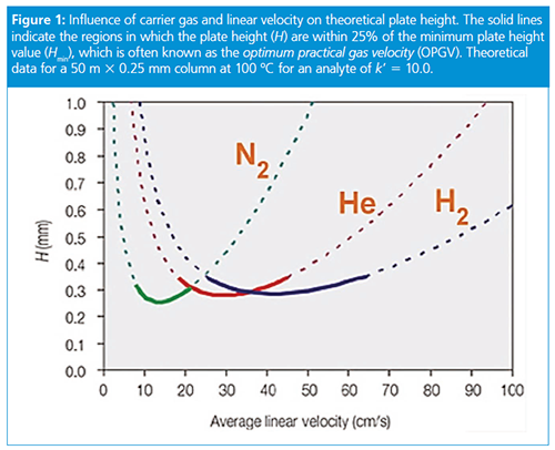
Although hydrogen is a convenient replacement for helium as a carrier gas, many chromatographers still have questions about method translation and performance.
Our starting point is that you already have a helium-based GC method that produces satisfactory resolution (selectivity) and now an equivalent hydrogen-based method is required.
A useful equation that describes the contributing factors to GC retention time and the ways in which the analysis speed might be altered is shown in equation 2:

Equation 2: Factors influencing retention in gas chromatography.
Where tR = retention time (as an indicator of analysis speed), L = column length (m), Å« = carrier linear velocity (cm/s), and k = retention factor.
When changing from helium to hydrogen as the GC carrier gas, changes in retention time can be expected. Reasons for this include:
- Hydrogen and helium separations optimize at different carrier gas velocities.
- The retention factor is influenced by the physicochemical properties of the gas (mobile phase).
- The best way to minimize those changes is to keep the same carrier gas velocity and phase ratio (ratio of column internal diameter to stationary phase film thickness) as in the original method.
In chromatographic terms, the appearance of the chromatogram (retention time, efficiency, resolution, and selectivity) is influenced by the choice of mobile phase. In GC, however, this effect is much less important than in high performance liquid chromatography (HPLC), as the GC carrier gas rarely interacts chemically with the stationary phase or with the analyte. The role of the carrier gas is mainly to transport the analyte in the gas phase through the column and to act as the second phase in the partitioning mechanism.
Undoubtedly, two properties of a carrier gas play a major role in the GC process: diffusivity and viscosity. The diffusivity of hydrogen and helium are roughly equal, but hydrogen is a bit less than half as viscous as helium at the same temperature (Figure 2). For this reason, hydrogen requires a lower pressure drop to achieve the same average carrier gas velocity as for helium.
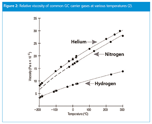
The relationship between linear velocity and pressure drop is somewhat nonlinear because of effects related to the compressibility of the carrier gas, but in general, the effect of switching from helium to hydrogen on retention time will be to cut retention times roughly in half if the inlet pressure is unchanged.
Retention times in GC are controlled by several factors: the distribution coefficient (K) of a solute in the column, which is not affected by the choice of carrier gas; the column dimensions (length, inner diameter, and stationary film thickness), all of which we will keep constant in this discussion; and the average carrier gas linear velocity (Å«). As the linear velocity increases, isothermal retention times decrease in exact proportion, so doubling the velocity cuts retention times in half.
Hydrogen requires a lower pressure drop to achieve the same average carrier gas velocity as for helium or nitrogen. For example, a 50 m × 250 μm column will deliver an average velocity of 60 cm/s at 100 °C with 58.6 psig (404 kPa) of helium or with 27 psig (186 kPa) of hydrogen; the situation is similar for nitrogen. If the linear velocity is unchanged with a hydrogen vs. helium carrier, then retention times remain the same too, while the inlet pressure that is required with hydrogen will be about half as much as with helium.
Conversely, if the same inlet pressure were applied with hydrogen as with helium, then the hydrogen carrier gas would cause peaks to be eluted in less time because the linear velocity would be faster than with helium. In the previous example, helium at 27 psig would have an average linear velocity of 29.4 cm/s and so with hydrogen carrier at the same pressure, all peaks retention times would decrease in the proportion 29.4/60 ≈ 0.5.
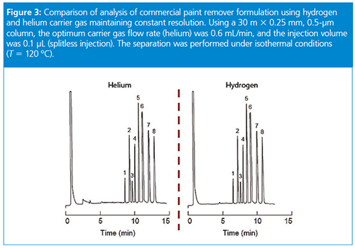
At constant flow rates, the situation is intermediate between the effects at constant velocity and those at constant pressure. At 27 psig of helium, the column flow rate is going to be 1.43 cm3/min and the average velocity will be 29.4 cm/s. The hydrogen carrier pressure required for the same flow rate will be about 16.3 psig (112.4 kPa), but now the average velocity will increase to 37.5 cm/s. Therefore, in this example, retention times will decrease by a factor of 29.4/37.5 = 0.78 for hydrogen compared with helium at the same column flow rate.
In summary: for isothermal operation at constant average linear velocity, retention times are not affected by changing the carrier gas. At constant inlet pressure, hydrogen carrier will cause peaks to be eluted in about half the time, and at constant flow rate retention times will be about 78% with hydrogen compared with helium. Most modern GC systems are capable of adjusting inlet pressure to achieve a target average linear velocity once the carrier gas type has been specified.
What if column temperature programming is used?
When changing from helium to hydrogen as the carrier gas, changes in retention time can be expected. The best way to minimize those changes when performing temperature programmed GC is to keep the same carrier gas velocity, temperature program, and phase ratio as in the original method. Please bear in mind that after method translation further optimization might still be required.
We should add the caveat that if the velocity is too high, solutes don’t spend enough time in the column for an efficient separation; if the velocity is too low, solutes broaden excessively by diffusion through the mobile phase. Further, large changes in carrier gas velocity during temperature programmed analysis can affect relative peak spacing (selectivity) and retention order may swap. If your instrument allows, chose to have the carrier programmed in “constant linear velocity mode”, which will help to avoid selectivity change issues.
If the instrument is operated at a constant head pressure, as the temperature increases, then the column flow decreases due to an increase in the viscosity of the carrier (Figure 4, 17). By taking advantage of computerized inlet pneumatics (sometimes called Electronic Pneumatic Control or similar), then as the temperature increases, the instrument increases the carrier pressure to maintain constant column flow (increasing linear velocity), which results in earlier elution of the more highly retained sample components (Figure 4, 24).
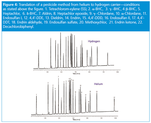
For ease of method translation, one might use one of the many GC method translation software tools that are available from the major equipment and column vendors. These tools allow the translation of not only the carrier gas settings pressure/flow settings but can also recommended a temperature programme to preserve elution order/resolution. Important: In order to use this software, the stationary-phase chemistry must remain the same for the old and translated methods.
Some useful translation tools can be found at the following links;
- https://www.agilent.com/en/support/gas-chromatography/gcmethodtranslation
- https://www.restek.com/Landing-Pages/EZGC-Calculators-and-Chromatogram-Modeler-for-GC-Method-Development
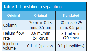
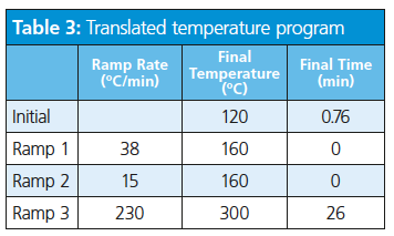
Consider the translation of a separation of target pesticide compounds using vendor software-based method translation (Tables 1, 2, and 3).

The role of hydrogen in GC is not limited to use as a carrier gas but extends to participating in the detection process either as a fuel or make-up gas. The use of hydrogen as a make-up gas or fuel gas is somewhat detector- and application-dependent.
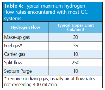
Table 4 lists typical maximum hydrogen flow rates encountered with most GC systems. This table also gives an indication of the gas flows that need to be considered when specifying the volumetric flow rate requirements for hydrogen generators. The maximum instantaneous flow rate requirements should be multiplied by the number of GC instruments being supplied.
Combustion Detectors: Before switching to hydrogen, you should bear in mind that GC combustion detectors (FID, nitrogen–phosphorus detector [NPD], and flame photometric detector [FPD]) work with hydrogen as the fuel gas, so any GC instrument equipped to work with such detectors is already fit to work with hydrogen (tubing and safety measurements in place).
Combustion detectors use four different gases:
- Carrier
- Make-up (detector- and applicationâdependent)
- Fuel (usually hydrogen)
- Oxidizing gas (usually air)
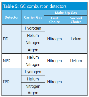
The stoichiometry of combustion (hydrogen to oxygen ratio) is vital in determining the sensitivity of the instrument and can be optimized for each analysis. The use of hydrogen as a carrier gas and as a fuel will impose restrictions on the make-up gas; this means, for as long as the stoichiometry of the combustion (hydrogen to oxygen ratio) is not affected, hydrogen is a valid make-up gas; otherwise an inert gas (such as nitrogen or helium) would be a better choice (Table 5).
Non-Combustion Detectors: Nonâcombustion detectors, such as TCD and ECD, will only use carrier and make-up gases. The selection of make-up gas is again instrument- and application-dependent.
TCD Considerations: Due to its inertness and high thermal conductivity, helium has been traditionally used as the carrier gas of choice for TCD; however, other gases such as nitrogen, argon, and hydrogen can also be used. The important thing is that thermalâconductivity detectors work best when there is a large difference in thermal conductivity between the sample and the carrier gas. As a consequence, the use of hydrogen for TCD is applicationâdependent.
The sensitivity of a TCD, however, is affected by the carrier gas. TCD response depends on a change of thermal conductivity between pure carrier gas and a mixture of carrier gas and a peak as it is eluted. Since hydrogen has about 1.2-times higher thermal conductivity than helium, peaks other than hydrogen or helium would be expected to be that much larger with hydrogen carrier, as long as pneumatic conditions were adjusted so that the peak shapes and positions were the same as with helium.
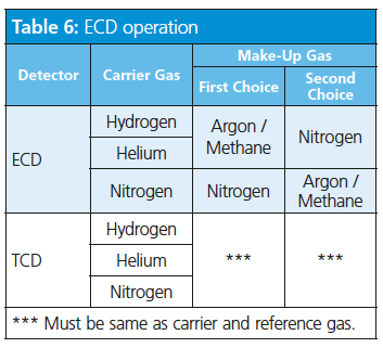
ECD Considerations: For optimum ECD operation, the carrier and make-up gas should be ionizable. Neither hydrogen nor helium ionize under the normal ECD operating conditions and should not be used as the make-up gas (Table 6).
References
- D. Cole-Hamilton, emeritus professor of chemistry at the University of St Andrews, UK, quoted in The Independent, Tuesday 22 January 2019, https://www.independent.co.uk/news/uk/home-news/helium-supply-world-shortage-run-out-recycle-mri-scanners-deep-sea-diving-balloons-a8741081.html
- J.V. Hinshaw, LCGC Asia Pacific12(2), 1100 (2009).
Tony Taylor is Group Technical Director of Crawford Scientific Group and CHROMacademy. His background is in pharmaceutical R&D and polymer chemistry, but he has spent the past 20 years in training and consulting, working with Crawford Scientific Group clients to ensure they attain the very best analytical science possible. He has trained and consulted with thousands of analytical chemists globally and is passionate about professional development in separation science, developing CHROMacademy as a means to provide high-quality online education to analytical chemists. His current research interests include HPLC column selectivity codification, advanced automated sample preparation, and LC–MS and GC–MS for materials characterization, especially in the field of extractables and leachables analysis.
E-mail:tony@crawfordscientific.comWebsite: www.chromatographyonline.com

Regulatory Deadlines and Supply Chain Challenges Take Center Stage in Nitrosamine Discussion
April 10th 2025During an LCGC International peer exchange, Aloka Srinivasan, Mayank Bhanti, and Amber Burch discussed the regulatory deadlines and supply chain challenges that come with nitrosamine analysis.


