The LCGC Blog: HPLC Diagnostic Skills—Noisy Baselines
In this instalment of the LCGC Blog, Tony Taylor discusses noisy baselines in high performance liquid chromatography (HPLC).
gonin/stock.adobe.com

In this instalment of the LCGC Blog, Tony Taylor discusses noisy baselines in high performance liquid chromatography (HPLC).
Just as medical practitioners are able to discern worrying features from a variety of medical physics devices (electrocardiogram, electroencephalogram, and ultrasound, for example), we need to develop the skill to identify worrying symptoms from our high performance liquid chromatography (HPLC) instrument output. Medical professionals learn an innate ability to identify critical symptoms (signals) from the noise or random variation in the instrument output, and we need to develop these same skills in order to avoid production of data not fit for purpose or instrument failure.
One of the most useful diagnostics in HPLC is the nature of the baseline produced by the detector while the eluent is flowing. While there can be many baseline characteristics such as drift, irregular, or more regulation cycling (pulsations), baseline noise is perhaps the most commonly encountered, and can arise from a variety of different sources. One needs to be aware of what constitutes “normal” baseline as opposed to unusual levels of baseline, depending upon the instrument configuration. Of course, the business imperative is not only to spot problems, but also to quickly and efficiently deal with them, and that is the subject of this blog.
The signal to noise (S/N) of the HPLC output is usually measured as the ratio of the detector signal to the inherent background signal variation and is a useful measure of the “normal” noise within the system. The inherent or background noise is typically measured over a predefined portion of the baseline, and most data systems will be capable of making this measurement and reporting the result.
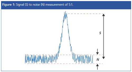
When inherent or background noise within the system is unusually high, this can affect system performance and will usually result in an increase in the limit of quantitation and issues with reproducible integration. This is why, as chromatographers, we get so worked up about noise levels that are higher than expected.
The smallest detectable signal is usually estimated to be equivalent to three times the height of the average baseline noise. This would give a S/N ratio of 3:1 for the “limit of detection” (LOD) of the detector. If the amount of analyte injected is less than this, then the signal ceases to be distinguishable from noise. For quantitative analysis a S/N ratio of 10:1 is recommended for the “limit of quantitation” (LOQ).
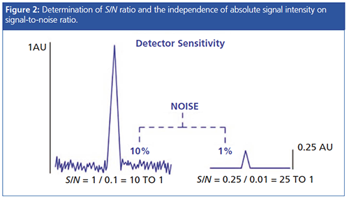
The magnitude of the analyte signal cannot be used in isolation when calculating detector sensitivity, the sensitivity of detection is usually defined in terms of S/N ratio-a measurement of the ratio of the analyte signal to the variation in baseline. S/N measurements are usually performed by the data system.
One needs to begin by establishing, preferably for each method and set of instrument conditions, the S/N when the method (or instrument) is performing well, and perhaps even set a system suitability performance criterion (usually a range or lower acceptable limit) for the determination.
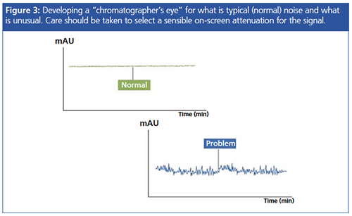
Of course, the seasoned chromatographer will typically know by glancing at the baseline whether the inherent noise is “usual”, and this comes only through experience. One should also take care to assess the noise at a reasonable screen magnification or signal attenuation, as any baseline can be made to appear noisy with the correct level of magnification!
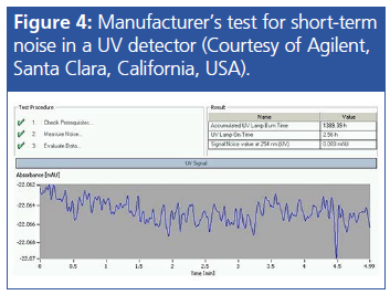
However, once again the data system may be able to help us out by reporting what is known as the peak-to-peak noise, which may be expressed as absorbance units. This measurement is of the variation in the normal baseline portion, rather than a ratio to the height of a signal, and can be very useful at establishing acceptable limits for the background noise. Most HPLC detectors will run a noise test evaluation as part of their initialization routine or can perform a longer test using ASTM criteria with HPLC-grade water flowing through the flow cell. Specifications for acceptable noise levels will be given in the manufacturer’s literature.
Although typically associated with detector phenomenon, there are many contributors to the noise within an HPLC system, and here we will examine just some of the main culprits. Noise can be both random and periodic depending upon the nature of the underlying cause of the problem, and this difference can, in itself, give us some clues to the nature of the issue.
Detector Noise
Electronic and Stray Light Noise: Every detector has associated background electronic and stray light noise, which is kept to a minimum through shielding of the optical bench with insulating materials. The in-built tests within the detector firmware should keep this to a minimum, and the instrument will flag up if any of these tests are failed on startâup. This is a good reason to cycle the power on the detector every now and then if your laboratory practice is to leave the detector powered on when not in use.
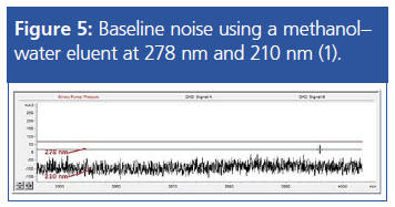
Detector Wavelength and Acquisition Settings: Lower wavelength settings (<220 nm) will inherently show an increase in noise that is associated with solvents (methanol absorbs up to 201 nm) and buffers that lower the amount of light falling onto the photodiode array. The noise of the detector is inversely proportional to the amount of light falling on the photodiodes, and therefore any other factors that decrease the amount of light falling onto the photodiode will also increase the noise within the output. Typically, this can include an ageing lamp or dirty flow-cell windows.
These problems may be overcome in the following ways:
- Follow your manufacturer’s instruction to clean or replace the flow-cell windows
- Perform a lamp intensity test (using on-board diagnostics) to assess lamp performance and replace the lamp if necessary
- Use acetonitrile instead of methanol as the organic modifier (methanol cut-off 210 nm)
- Avoid using highly absorbing buffers and additives that include (UV cut-off shown in brackets for a 10 mM solution): TFA (0.1% TFA shows much lower absorbance at 214 nm than 210 nm), citrate (230 nm), acetate (210 nm), formate (210 nm)
- Optimizing the compressibility and stoke volume settings of the pump to minimize the noise based on the compressibility of the solvents used.
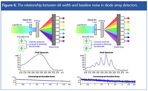
Most diode array UV detectors have a slit width setting that describes the width of the slit that focuses light onto the photodiode after passing through the flow cell. As the slit width is increased, the light becomes more diffuse and each wavelength falls over a number of photodiodes (corresponding to the slit width setting). This reduces the noise of the baseline while increasing the signal intensity and so gives greater analytical sensitivity when quantifying analytes. However, the spectral resolution necessary for qualitative analysis (peak track via library matching, for example) is lost, and so it needs a much narrower slit width setting so that the light is less diffuse and each wavelength falls on a smaller number of diodes. When slit width is reduced, the noise level increases, and one needs to set width according to the analytical requirements.
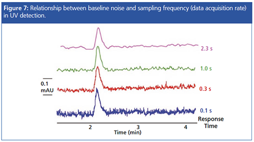
The detector acquisition rate and data bunching may also have a profound effect on signal noise according to the following relationship:

Where n is the number of data points. Simply put, the more measurements that are taken, the better that we model the random variations associated with instrument response change and the noise becomes better resolved. One needs to carefully balance the S/N ratio with the actual peak to peak noise generated, which is usually achieved using the instrument response or frequency. This needs to be further balanced with the number of data points acquired across each peak, which should be in the region of 20–25 or higher for UV data.
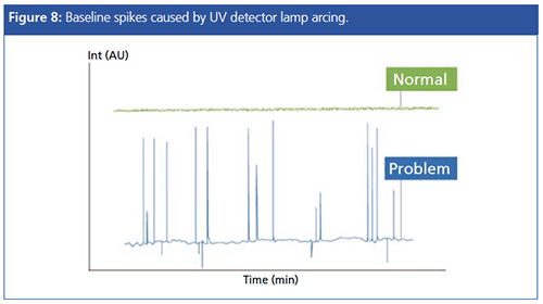
As alluded to earlier, the deuterium lamp within the UV has a finite lifetime, and can lead to not only an increase of baseline noise, but also to spikes as the lamp arcs against the metal casing onto which the filament is mounted. This gives a baseline appearance similar to that shown in Figure 8, and one needs to consider lamp replacement to judge if the spiking is due to the age of the lamp. Note that other causes of baseline spikes (such as a poorly shielded electrical supply or power board within the detector) are also possible.
Spikes can be distinguished from “real” peaks as they will have no Gaussian shape when zoomed in
Other Sources of Noise
Improper Mixing: HPLC UV detectors can be very susceptible to improper mixing of mobile phases, which are formed on-line via either binary or quaternary pumping systems. The absorbance changes as a result of poor mixing are usually associated with a sinusoidal pulse (covered in a future blog); however, at lower pumping volumes or when using additives such as TFA, the disturbances can resemble noise rather than a discernible sinusoidal pulse.
Figure 9 shows the differences made to the baseline appearance of a 0.1% TFA gradient with various mixer volumes.
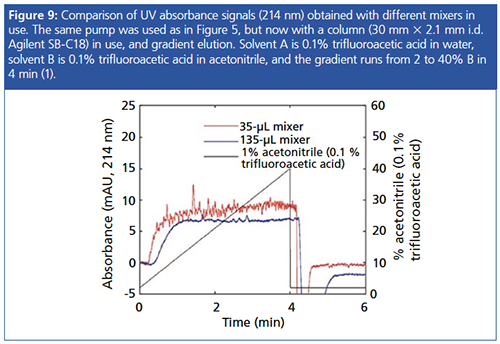
Even though modern HPLC instruments are designed with high-efficiency mixers, the addition of a post-market static mixer or simple in-line filter can help to drastically reduce the baseline noise under the circumstances described above. One should note that the additional extracolumn volume contributed by the fitting of inâline mixers may have a detrimental effect on peak width, especially in ultrahighâpressure liquid chromatography (UHPLC) systems, and one needs to balance any increase in peak width with the reduction in baseline noise when assessing the S/N characteristics of the method.
One should further note that very similar noise characteristics can also be obtained from failing quaternary pump gradient proportioning valves.
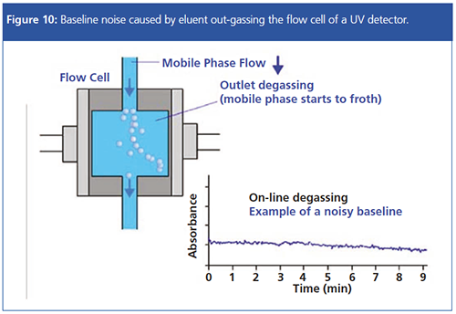
Lack of Degassing: If the mobile phase is poorly degassed, small bubbles may outgas from the mobile phase as the eluent enters the flow cell of the detector, due to the pressure change that occurs. This “frothing” of the mobile phase can cause significant baseline noise, and while detector flow cells are designed with a back-pressure restriction to reduce the pressure reduction on entering the flow cell, this can be ineffective when the eluent is not properly degassed.
One needs to ensure that the eluent is properly degassed using on-line degassing modules and, in some cases, by degassing using vacuum methods prior to mounting onto the HPLC system.
Dewetting: If the HPLC column contains residual packing solvents or has been used with immiscible solvents (for example, in normal phase mode), then improper flushing of the column can lead to increased baseline noise associated with dewetting phenomenon.
Equilibrate the column for several hours at the method flow rate to completely flush the column of any immiscible solvents.
References
- https://www.researchgate.net/post/How_can_a_very_high_noise_signal_in_HPLC_Diode_Array_detector_be_explained
- http://www.chromatographyonline.com/mixing-and-mixers-liquid-chromatography-why-when-and-how-much-part-i-pump?pageID=3
Tony Taylor is the technical director of Crawford Scientific and CHROMacademy. He comes from a pharmaceutical background and has many years research and development experience in small molecule analysis and bioanalysis using LC, GC, and hyphenated MS techniques. He is actively involved in method development within the analytical services laboratory at Crawford Scientific and continues to research in LC–MS and GC–MS methods for structural characterization. As the technical director of CHROMacademy, he has spent the past 12 years as a trainer and developing on-line education materials in analytical chemistry techniques.
E-mail:tony@crawfordscientific.comWebsite:www.chromatographyonline.com

New Study Reviews Chromatography Methods for Flavonoid Analysis
April 21st 2025Flavonoids are widely used metabolites that carry out various functions in different industries, such as food and cosmetics. Detecting, separating, and quantifying them in fruit species can be a complicated process.
Extracting Estrogenic Hormones Using Rotating Disk and Modified Clays
April 14th 2025University of Caldas and University of Chile researchers extracted estrogenic hormones from wastewater samples using rotating disk sorption extraction. After extraction, the concentrated analytes were measured using liquid chromatography coupled with photodiode array detection (HPLC-PDA).

.png&w=3840&q=75)

.png&w=3840&q=75)


.png&w=3840&q=75)


.png&w=3840&q=75)


