How Does It Work? Part 1: Pumps
Understanding how liquid chromatography pumps operate can help streamline solving pump problems.
John W. Dolan, LC Troubleshooting Editor
Understanding how liquid chromatography pumps operate can help streamline solving pump problems.
It is possible to obtain very satisfactory quantitative results from a liquid chromatography (LC) analysis by following an established method, preparing the samples, placing them on the LC system, and after they have been analyzed, processing the collected data. However, when things don’t go as expected, I believe you’ll be most successful at troubleshooting if you have two knowledge sets in your mental toolbox: knowledge of how the various instrument components work and knowledge of the basic principles of the chromatographic process. Unfortunately, when problems occur, time constraints often do not allow us to take the time to obtain this knowledge. Thus, it is best to make a habit of gradually gaining this knowledge and reviewing it periodically, so it will serve you well when you need it. For this reason, I’m embarking on a series of discussions of how the components of an LC system work. Most of this description will be generic in nature, but it should be obvious how it applies to particular brands and models of equipment in your laboratory, whether these have been in use for 20 years or they are the latest ultrahigh-pressure LC (UHPLC) systems.
This month’s “LC Troubleshooting” discussion focuses on the pump that drives the mobile phase through the system. We also consider a little history on pump development and describe the two most common pump designs in use today.
Basic Design
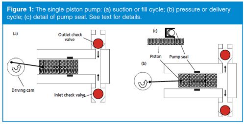
All LC pumps in use today are based on the reciprocating piston design shown in Figure 1. The basic elements of the pump are a cylindrical pump chamber that holds the piston, a motor that operates a driving cam, a pump seal, and a pair of check valves. As the motor rotates, the piston is moved in and out of the pump chamber. In most pump designs, the pistons are made of sapphire, but stainless steel and graphite are sometimes used. The check valves serve to control the direction of flow of mobile phase through the pump (flow is from bottom to top in all the figures). In their simplest form, the valves comprise a ruby ball and a sapphire seat that is slightly ground (“lapped”) to ensure a leak-free seal when the ball rests on the seat. The valves open and close in response to pressure and gravity. The pump seal keeps mobile phase from leaking out around the piston when the pump is under pressure and keeps air from leaking in when the pump is filling.

On the inlet stroke of the pump (Figure 1[a]), the piston moves out of the pump chamber. This creates a low pressure region in the chamber, which allows the outlet check valve to settle onto its seat and a slight siphon pressure from the mobile phase reservoir plus the low pressure inside the pump chamber causes the inlet check valve to rise off of its seat and allow mobile phase to enter the pump chamber.
The piston reverses direction during the pressure, or delivery stroke of the pump (Figure 1[b]). The increased pressure inside the pump chamber causes the inlet check valve to close, and when the pressure inside the pump exceeds the pressure downstream, the outlet check valve is forced open and mobile phase flows towards the column.
The pump seal comprises a polymeric ring encircling the piston. The crossâsection of the seal in Figure 1(c) shows a groove that contains a spring on the high-pressure side of the seal. The spring helps to pull the lip of the seal against the piston to make better contact and is aided by the high liquid pressure in the pump chamber that also pushes the lip of the seal against the surface of the piston. Thus, the seal acts much like a squeegee to keep the mobile phase within the pump chamber. However, the sealing process isn’t perfect, but allows a thin film of mobile phase to remain on the piston surface and thus lubricate the piston-seal interface so the seal does not wear out prematurely.
A pump that was not much more sophisticated than that of Figure 1 was a common component of early LC systems. The first LC system I used in 1972 was a lab-built system that contained a Milton-Roy MiniPump that was distributed by Laboratory Data Control. The flow rate was controlled by adjusting the stroke of the piston using a large micrometer mounted on the pump.
One huge problem with the simple single-piston reciprocating pump is that it spends half its time filling and half the time delivering mobile phase. This means that it will have large pulses in flow and pressure - both defects that are not desirable for the constant flow and even pressure required for satisfactory detector performance. Early systems that relied on the MiniPump often incorporated pulse dampers in the form of a gas ballast, Bourdon tube, or mechanical pressure gauge. Later innovations included elaborately shaped driving cams and variable-speed motors that reduced the fill portion of the pump cycle and smoothed the delivery. Although the designs were clever and were great improvements over the original pumps, they could not fully correct the flow and pressure problems inherent in single-piston pumps.
Enter the Dual-Piston Pump
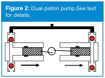
There is a very simple way to overcome the flow and delivery pulses of the single-piston pump - just use two pumps operating 180° out of phase. A conceptual diagram of this setup is shown in Figure 2. In this case, two pumps are driven from a single cam. While one pump head fills (left in Figure 2), the other delivers (right). The combined output of the pumps (top of Figure 2) should be constant: when one pump head fills, the other is delivering. With a bit of fine-tuning of the design, this type of LC pump is very effective. For example, the pistons are usually mounted parallel to each other, much like an automobile engine, and are driven off of a single camshaft. The dual-piston pump is at the centre of many of today’s LC and UHPLC systems.

An Alternate Design
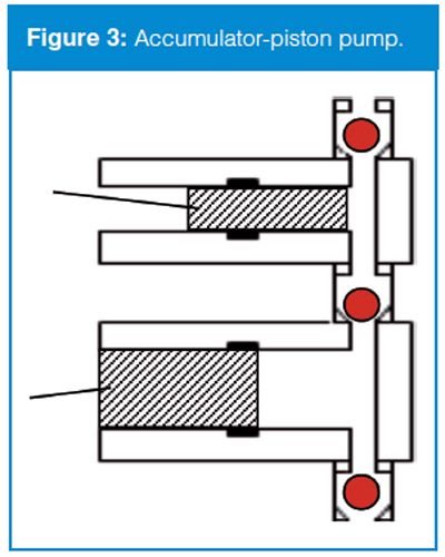
Another way to use two pistons in a single pump is to operate them in tandem instead of parallel. This is usually referred to as the accumulatorâpiston design and is shown in Figure 3. Here, the two pistons deliver at different rates. For example, let’s say that we want a flow rate of 1 mL/min; the top piston will operate at 1 mL/min and the bottom one at 2 mL/min. There are three check valves, an outlet (top) and an inlet (bottom) plus a middle check valve that acts as in inlet check valve for the top piston, but an outlet check valve for the bottom piston. In the cycle shown in Figure 3, the top piston delivers 1 mL/min to the column, with the outlet check valve open and the middle check valve closed, just as if it were a single-piston pump. Meanwhile, the bottom piston fills at 2 mL/min with an inlet check valve open and the middle check valve closed. On the alternate cycle (not shown), the bottom piston delivers at 2 mL/min; 1 mL/min serves to fill the top piston and the other 1 mL/min flows to the column. Thus, 1 mL/min of mobile phase always flows to the column. The accumulatorâpiston pump is also a very popular pump in modern LC and UHPLC systems.

More on Check Valves
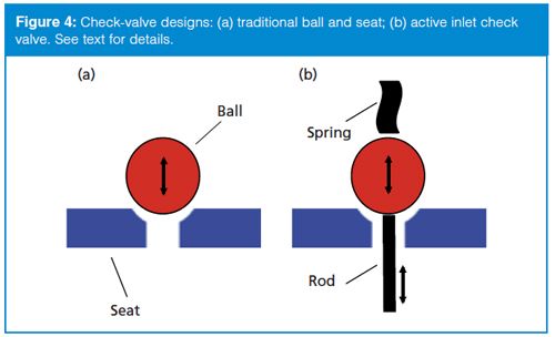
The check valves are critical to the operation of the pump, yet they tend to be the least reliable parts. Let’s take a closer look at the check valves next. The most common check valve design comprises a ruby ball and sapphire seat, as illustrated in Figure 4(a). The seat is slightly ground or “lapped” to match the curvature of the ball for better sealing (this is exaggerated in the figure for illustrative purposes). When the pressure below the check valve is higher than above it, the ball is lifted from the seat and solvent flows through the hole in the seat. When the pressure is equal on both sides of the valve or higher on the top, the ball settles onto the seat and provides a seal. As long as the surfaces of both components are clean, this combination can provide effective sealing, even at UHPLC pressures of >1000 bar (>14,500 psi).

Even with reliable sealing, it is desirable to minimize the number of check valves in a pump. It can be seen in Figure 3 that there are only three check valves in the accumulatorâpiston pump as compared to four in the dualâpiston design (Figure 2). Fewer check valves should mean better reliability, at least in theory, and this is certainly argued by the manufacturers of accumulator-piston pumps.
Another problem that can arise with check valves is related to acetonitrile as a solvent. “Pure” HPLC-grade acetonitrile has minor contaminants that can polymerize on the sapphire surface of the valve seat, causing the ball to stick to the seat because of surface tension effects. One way to overcome this problem is to occasionally sonicate the inlet check valves in methanol. Another approach is to use another check-valve material, such as ceramic, but this approach does not seem to give as leak-free a seal as the ruby-sapphire combination. (Read more about the acetonitrile problem in reference 1.)
Sticking is usually a problem only with the inlet check valves, because the pressure within the pump is sufficient to force open the outlet check valve. Many pumps today contain “active” check valves on the pump inlet. The principle of this design is shown in Figure 4(b), where mechanical assistance is added to the normal ball-type valve. A spring above the ball helps ensure that it is seated properly when the valve is closed. Below the ball, a solenoidâactuated lifting device is added. In the illustration, a rod is pushed against the bottom of the ball, forcing it off the seat. This rod moves up and down under solenoid control to open the valve or allow it to close with the assistance of the spring. The active check valve is not subject to sticking when using acetonitrile, so it is more reliable. The inlet check valves of many of today’s LC and UHPLC pumps use active check valves, whether the dualâpiston or accumulator-piston design is used.
One additional observation about the accumulator-piston pump (Figure 3) is that the outlet (top) check valve should always be open. This is because either the top or bottom piston is always supplying flow to the column. If this is the case, there is no need for an outlet check valve, and often it is not included on this pump design. So with no outlet check valve and an active inlet check valve, the accumulator-piston pump often has only one traditional ball-type check valve between the two piston chambers. The comparable dual-piston pump would have two active inlet check valves and two traditional outlet check valves. Although it would seem from this description that the accumulatorâpiston design is superior, there are other nuances of pump design that are important too. In my experience, the two designs give very similar performance. If you want more information on why one design is superior to the other, just talk to the appropriate manufacturer . . . but you may gather more information than you know how to use.
Maintenance
Before we close this discussion, let’s touch on a few maintenance-related topics. As with any other part of the LC system, the pump requires periodic maintenance for reliable operation. It is a good idea to perform annual preventive maintenance on all LC pumps, even if they are not used very heavily. For laboratories that use their systems continuously, semiannual or even more frequent maintenance may be desirable.
Cleanliness is the primary key to reliable pump operation. For this reason, you should be sure that the pump is never stored in solvents that will promote microbial growth or corrode the system. Usually this practice means removing any aqueous solutions or buffers from the system when it is not in use. Buffers can evaporate and leave deposits in the system, and buffer solutions can be ideal growth media for bacteria. Biological contaminants or insoluble materials can coat the checkâvalve balls or seats, preventing proper sealing. Physical blockage of the column or contamination of the column packing can occur under these conditions, as well. A simple way to avoid most of these problems is to flush salt- and buffer-containing solutions from the LC system when it is not in use. Rinse the system with high performance liquid chromatography (HPLC)-grade water, then store it in the organic solvent used in the mobile phase (usually methanol or acetonitrile).
Pump seals will often last a year or longer if the pump is rinsed regularly. I like to replace the seals annually at a minimum. Be sure to replace the seals with the correct part number item; some vendors sell seals of different composition for different applications and sometimes the wrong seal can create additional problems. If you are using UHPLC and the manufacturer recommends a seal-wash routine, use it. This procedure provides a small flow of solvent (often water) on the low-pressure side of the pump seal. This helps to dissolve contaminants from the piston surface, give additional lubrication, and, in the case of UHPLC, may cool the piston so that the seal does not melt due to the heat generated under the extreme pressure of UHPLC operation.
Check valves should not require special care if the pump is flushed regularly. If your pump has the traditional ballâtype valves (Figure 4[a]) and you use 100% acetonitrile, you may have to institute a sonication routine if check-valve sticking becomes a problem. Check valves can be replaced, but with proper care this is seldom required.
When setting up a preventive maintenance programme, be sure to consult the operation and service manual for the pump. Some designs of pumps require periodic lubrication or other routine service.
Summary
The basic components of HPLC pumps have not changed much since the introduction of modern liquid chromatography in the 1960s. Many refinements in design and manufacture over the years have made pumps much more reliable than they were in the past. Good “chromatographic hygiene” will go a long way towards keeping the pumping portion of your LC system reliable and trouble-free.
References
- J.W. Dolan, LCGC North Am.26(6), 532–538 (2008).
“LC Troubleshooting” Editor John Dolan has been writing “LC Troubleshooting” for LCGC for more than 30 years. One of the industry’s most respected professionals, John is currently the Vice President of and a principal instructor for LC Resources in Lafayette, California, USA. He is also a member of LCGC Europe’s editorial advisory board. Direct correspondence about this column should go to John.Dolan@LCResources.com. To contact the editorial team please address any correspondence to: “LC Troubleshooting”, LCGC Europe, Hinderton Point, Lloyd Drive, Ellesmere Port, CH65 9HQ, UK, or e-mail the editorâinâchief, Alasdair Matheson, at amatheson@advanstar.com

Characterizing Plant Polysaccharides Using Size-Exclusion Chromatography
April 4th 2025With green chemistry becoming more standardized, Leena Pitkänen of Aalto University analyzed how useful size-exclusion chromatography (SEC) and asymmetric flow field-flow fractionation (AF4) could be in characterizing plant polysaccharides.
Investigating the Protective Effects of Frankincense Oil on Wound Healing with GC–MS
April 2nd 2025Frankincense essential oil is known for its anti-inflammatory, antioxidant, and therapeutic properties. A recent study investigated the protective effects of the oil in an excision wound model in rats, focusing on oxidative stress reduction, inflammatory cytokine modulation, and caspase-3 regulation; chemical composition of the oil was analyzed using gas chromatography–mass spectrometry (GC–MS).


