Essentials of LC Troubleshooting, Part 2: Misbehaving Retention Times
Several liquid chromatography (LC) troubleshooting topics never get old because there are some problems that persist in the practice of LC, even as instrument technology improves over time. There are many ways for things to go wrong in an LC system that ultimately manifest as deviations from expected retention times. Developing a short list of the likely causes of these deviations can help streamline our troubleshooting experience when retention-related problems occur.
Writing this “LC Troubleshooting” column and thinking about topics each month is interesting in the sense that there are some topics that never get old. Although certain topics or ideas become obsolete once they are displaced by newer and better ideas in the chromatography research world, there are certain topics in the troubleshooting world that have remained relevant since the first troubleshooting article appeared in this magazine(LC Magazine at that time) in 1983 (1). Over the last few years, I’ve focused several “LC Troubleshooting” instalments on contemporary trends (the relatively recent advances in our understanding of the effects of pressure on retention [2]) in liquid chromatography (LC) that are affecting the way we approach our interpretation of LC results and approach troubleshooting with modern LC instruments. In this instalment, I am continuing a series I started in January of 2022 (3) that focuses on some of the “bread and butter” topics of LC troubleshooting—those elements that are essential for any troubleshooter, no matter the vintage of the system we are working with. The topics at the heart of this series are highly related to the well-known “LC Troubleshooting” wall chart (4) that hangs in many laboratories. For the second instalment in this series, I focus on problems related to retention (too low, too high, and changing unexpectedly) in reversed-phase LC separations. I hope LC users young and old will find some useful tips and reminders related to this important topic.
Everything is Possible
More often than not, I find myself responding to troubleshooting questions with “everything is possible”, which might seem like an easy out when considering observations that are hard to explain. However, I find that this response is appropriate more often than not. LCGC’s “LC Troubleshooting” wallchart lists no less than 18 possible causes for retention to be too high, too low, or changing. One could surely add to this list if the size of the wallchart were not a constraint and if we wanted to be really thorough. The main point is that it is important to keep an open mind when thinking of reasons that the observed retention is not right.
What Is To Be Expected?
A critical step in any troubleshooting exercise—but one that I think is unappreciated—is recognizing that there is a problem to be solved. Recognizing that there is a problem usually amounts to recognizing that what is happening with the instrument is different from what is expected to happen, and our expectations are formed from theories, empirical knowledge, and experience (5).
Before getting into details about what we can expect about retention, a few words to clarify what retention is and how it is measured are warranted. First, retention time (tr) is directly observable from a chromatogram, and is most commonly taken as the time corresponding to the apex of the chromatographic peak. Second, retention factor (k) is a commonly used measure of retention that is calculated from measurements of the retention time of a retained analyte (tr) and the column “dead time” (tm, or t0), which is a measure of the elution time of an “unretained” marker compound.

Although accurate determination of k is challenging because of the difficulty of obtaining accurate dead time values (6), there are several advantages of k over tr, some of which lead to more repeatable and reproducible measures of retention over time and between laboratories and instruments:
k is nominally independent of parameters including flow rate, column length, column diameter, and particle size, which makes comparing retention under conditions where these parameters are varied more straightforward than directly comparing retention times.
Small changes in flow rate because of changes in pump performance— which do directly affect tr—have little effect on k because the effect of a small change in the flow rate on retention will be similar to the effect on the dead time, and thus, the differences cancel out.
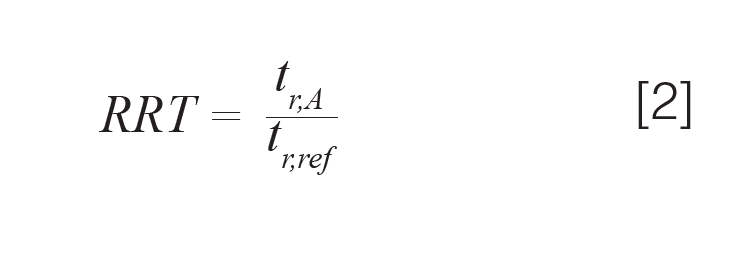
Finally, a third measure of retention that is common in practice is relative retention time (RRT):

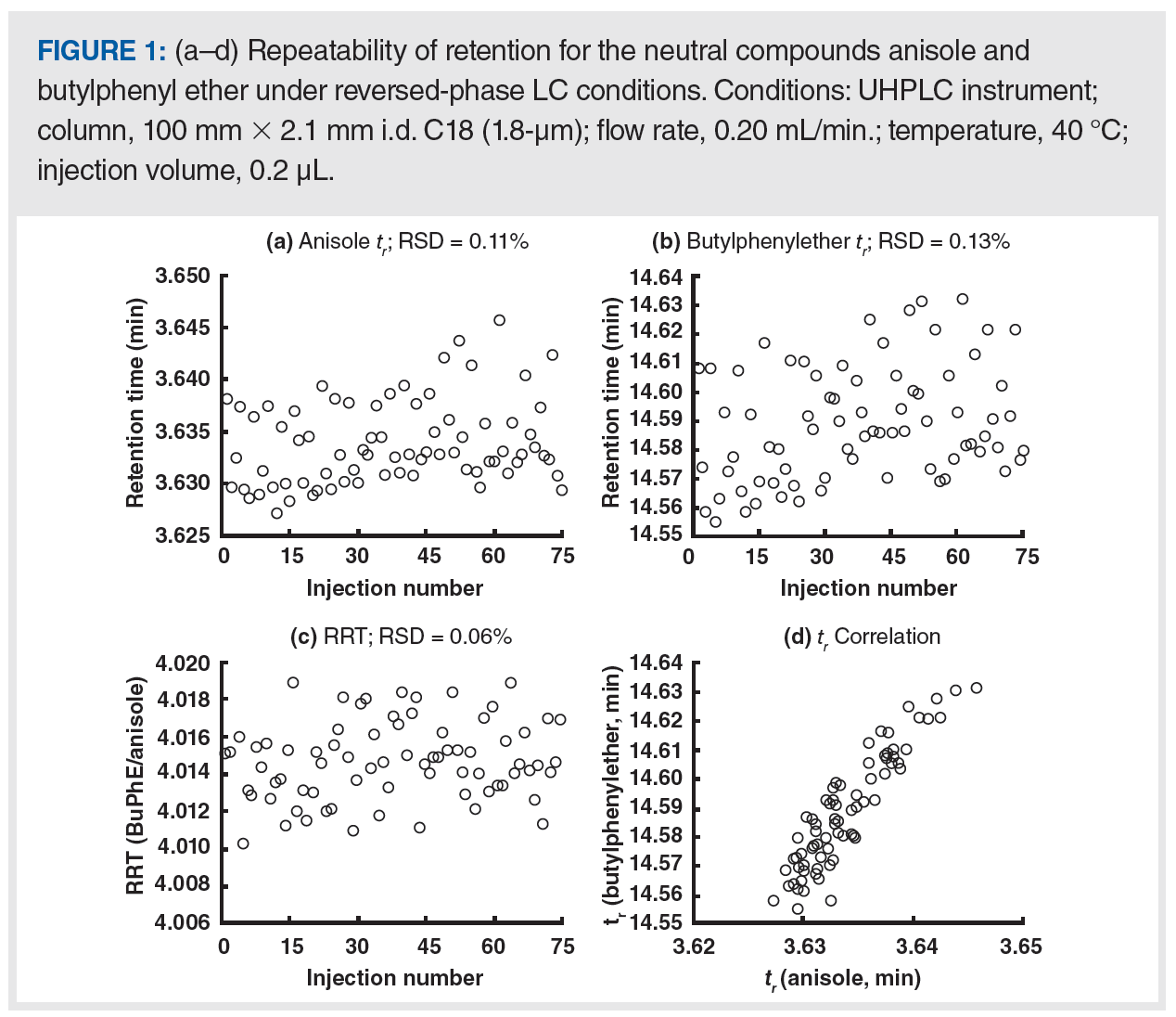
The RRT carries many of the advantages of k over tr, without the difficulty associated with accurate determination of column dead time. Figure 1 shows retention data from some recent isocratic measurements under reversed-phase conditions in my laboratory. Panels A and B show retention times obtained for anisole (A) and butylphenyl ether (B) from 75 replicate injections over a period of approximately 48 h. The relative standard deviations (RSD) of the retention times are 0.11% and 0.13%, respectively. Although these RSDs are reflective of the excellent retention stability we can expect from ultrahigh-performance LC (UHPLC), panel C shows that the RRT can be even more stable. In this case, we see that the RSD drops by nearly one-half to 0.06%. Panel D shows that the tr for the two compounds are highly correlated (the two compounds were injected as a mixture for each replicate injection), which is why the RRT is more repeatable than the tr in this instance.

Bearing in mind these details about the different ways of measuring retention, it is important to understand that there is no single standard we can use to judge whether the retention we see in a routine assay today is reasonable relative to prior work. Different applications with different conditions run on different instruments and in different laboratories will be characterized by different levels of variability in retention. Although the repeatability of retention shown in Figure 1 is excellent, it will not always be this good, even when using the finest equipment. The user must be aware of what constitutes “typical” performance. In the best-case scenario, a control chart or some other indicator of retention over time (days, weeks, or months) is used. It is only against this background that one can assess whether a retention observation today seems too low or high, or is varying too much.
Situations Involving Retention That Is Decreasing or Lower Than Expected
There are a few common potential causes of retention that either appears to be too low or decreasing over time.
Loss of Stationary Phase: Harsh mobile phase conditions can lead to loss of the component of the stationary phase that imparts retentive properties to the packing material. In reversed-phase LC, we frequently refer to this as the “bonded phase”, and for silica-based materials, this bonded phase is a ligand covalently bonded to the silica surface through siloxane (Si–O–Si) bonds. These bonds are susceptible to hydrolysis under acidic conditions (pH <2), and once the bond is hydrolyzed, the ligand can be washed out of the column, leading to a decrease in retention (7). This process manifests as a slow loss of retention over days or weeks, rather than a sudden, abrupt decrease in retention. Confirming that this is, in fact, happening is difficult. However, if such phase loss is suspected, it is best to adjust the mobile phase conditions to a less acidic pH, use a different, more chemically stable stationary phase, or both.
Mass Overload: If gradually decreasing retention is observed as the mass of analyte injected is increased (but the injection volume is constant), this could be a sign of mass overload (8). Mass overload can be a complex phenomenon, but one mechanism that seems to occur for charged analytes involves mutual repulsion of injected analytes by charged compounds already adsorbed to the stationary phase surface. One potential solution to this problem is to increase the ionic strength of the mobile phase; ionized mobile phase components (for example, sodium or ammonium ions) can interrupt the charge-repulsion mechanism and minimize the effect of the injected mass of analyte on retention time.
Volume Overload: The composition of the matrix of the injected sample can also have a dramatic effect on apparent tr. For example, in reversed-phase LC, if the sample contains more organic solvent than the mobile phase, this can lead to a decrease in retention (9). In hydrophilic interaction liquid chromatography (HILIC) separations, the same effect can be observed, but in this case, samples that contain more water than the mobile phase lead to a decrease in retention (10). Whereas the effect of mass overload on retention tends to be gradual, with volume overload the change in retention can be sudden and dramatic because of a “breakthrough” of the analyte band as some of it travels with the band of sample solvent through the column (11). This effect is relatively easy to study by varying the volume and composition of the injected sample over ranges of interest to the application at hand and looking for a correlation with the observed tr. If volume overload appears to be a problem, a variety of approaches can be used to mitigate this effect, including decreasing the injection volume, preparing the sample with less “strong solvent” (10), or installing a mixer between the injector and the column (12).
Stationary Phase Dewetting: Most stationary phases designed for reversed-phase LC are, by design, quite hydrophobic. When highly aqueous mobile phases (<2% organic solvent) are used with the phases, the mobile phase can actually be physically expelled from the narrow pores of the particles because of the low thermodynamic favorability of the highly aqueous phase interacting with the highly hydrophobic stationary phase (13,14). This process leads to an apparent loss of retention because analytes simply cannot diffuse into pores that have no solvent in them. This type of retention loss is usually sudden. The good news is that it is reversible by simply flushing the column with a few column volumes of mobile phase rich in organic solvent, and that is usually sufficient in restoring retention (13). This problem can be avoided by not using purely aqueous mobile phases with highly hydrophobic reversed-phase phases (for example, C8, C18, or phenyl). If highly aqueous mobile phases must be used, then more hydrophilic reversed-phase phases should be considered (for example, C1 or CN).
Situations Involving Retention That Is Increasing or Higher Than Expected
There are a few common potential causes of retention that either appears to be too high or increases over time.
Decreasing Flow Rate: If the flow rate through the LC column has decreased, or is slowly decreasing over time, the tr of an analyte will be higher than expected or slowly increase. Such a decrease in flow rate could be because of leaks outside of the pump (for example, connection to the column, sampler needle seat, sampler valve rotor seal), in which case the pump is working properly but not all of the mobile phase actually goes through the column. Also, the pump itself may not be producing the flow rate indicated by the software because of a leaky check valve or piston seal (3). These decreases in flow rate could be sudden or gradual depending on the root cause of the change. If decreasing flow rate is the suspected cause of increasing retention, it is helpful to compare both tr and retention factor (or RRT) to historical values. Whereas tr is dependent on flow rate, retention factor and RRT should be independent of flow rate. If a difference in the dependence of tr and k on flow rate is observed here, this difference is an important clue. Resolving the problem may or may not be tricky depending on the exact cause.
Leaky check valves do not produce leaks that we can see with our eyes in a way that a leaky needle seat or column connection would (see [3] for suggestions about troubleshooting leaky check valves). If the nominal flow rate is 2 mL/min, then a leak of 5% (100 µL/min.) because of a poor connection should be easy to spot. However, if the flow rate is 50 µL/min, then a leak rate of 5% only corresponds to 2.5 µL/min, which is harder to spot.
Changing Mobile Phase Composition: Given the strong dependence of retention on the mobile phase composition in reversed-phase LC, small changes in the mobile phase delivered by the pump can significantly increase or decrease retention. Changes in the composition delivered by the pump could be because of a leaky check valve in just one of the two channels of a binary pump. For example, if the acetonitrile channel is leaky,
then the contribution of organic solvent to the mobile phase will be lower than expected, and retention will increase. In pumps (usually quaternary) that use electric solenoids to open and close the flow path between a solvent bottle and the pump, a valve that fails to open correctly will lead to changes in the composition of the mobile phase delivered to the column (see [15] for differences between these pump designs). In this case, both tr and retention factor would be affected, but RRT would not be as affected. Comparing all three values to historical data may provide important clues. The control software used with modern LC instruments has built-in diagnostic tests that can be used to determine whether or not the pump is delivering the expected mobile phase composition both accurately and precisely (16).
Situations Involving Retention That Appears to Be Fluctuating
The “LC Troubleshooting” wallchart lists 11 different potential causes for fluctuating retention. Here, I discuss the two that I see causing problems most frequently.
Inadequate Buffering of the Mobile Phase pH: Retention of ionogenic compounds that have a pKa in the range of pH values normally used in reversed-phase LC (that is, from 2–10) can be sensitive to small changes in mobile phase pH. When working with these compounds, it is important to use a buffer with a good buffer capacity (typically more than 10 mM of the buffering agent, such as phosphate or formate), and under conditions where the target pH is within 1 pH unit of the pKa of the buffering agent. For example, the pKa of formic acid is approximately 3.8 in water, so formate buffers should only be used in the range between 2.8–4.8. Working outside of this range, or with a too low concentration of the buffering agent, would hinder the ability of the buffer to do its job. In other words, it would not be a buffer at all, and it would not be able to stabilize the mobile phase pH.
Uncontrolled Column Temperature:The retention of most compounds analyzed by reversed-phase LC decreases with increasing column temperature, thus the stability of retention over time is dependent on the stability of the column temperature over time. Most modern LC instruments have the capacity both to preheat the mobile phase before it enters the column and to control the temperature of the column environment (17). However, some instruments are used without these features, and this can be a source of variability in retention. For some highly sensitive compounds, retention can vary because of temperature fluctuations even with state-of-the-art LC equipment. In these cases, controlling the room temperature as tightly as practically possible is helpful (18).
Summary
In this second instalment on essential topics in LC troubleshooting, I discussed situations where the observed analyte retention is somehow different from what is expected or normal. Effective troubleshooting for this type of problem begins with a sense for what the expected retention behaviour is, so that a deviation from those expectations is noticeable. There are many different potential causes of retention related problems (too low, too high, or varying). In this instalment, I discussed some of the causes I see most frequently in detail. Understanding these details provides a good place to start troubleshooting but does not capture all possibilities. Readers interested in learning about a deeper list of causes and solutions are referred to the “LC Troubleshooting” wallchart.
Acknowledgements
I would like to thank Tina Dahlseid and Carter Henning for their effort in collecting the data shown in Figure 1.
References
- D. Runser, LCGC 1, 10–16 (1983).
- T. Kempen and D.R. Stoll, LCGC Europe 34(10), 419–423 (2021).
- D.R. Stoll, LCGC Europe 35(1), 16–20 (2022).
- LCGC Troubleshooting Wallchart. https://www.chromatographyonline.com/view/troubleshooting-wallchart.
- D.R. Stoll, LCGC Europe 33(10), 505–509 (2020).
- D. Cabooter, H. Song, D. Makey, D. Sadriaj, M. Dittmann, D. Stoll, and G. Desmet, J. Chromatogr. A. 1637, 461852 (2021). https://doi.org/10.1016/j.chroma.2020.461852.
- J.W. Dolan, LCGC Europe 29(2), 82–84 (2016).
- D.V. McCalley and D.R. Stoll, LCGC Europe 34(12), 508–511 (2021).
- D.R. Stoll and A. Mack, LCGC Europe 32(9), 484–489 (2019).
- D.R. Stoll, LCGC Europe 32(1), 16–20 (2019).
- S. Chapel, F. Rouvière, V. Peppermans, G. Desmet, and S. Heinisch, J. Chromatogr. A. 1653, 462399 (2021). https://doi.org/10.1016/j.chroma.2021.462399.
- Z. Breitbach, C. Randstrom, J. Chang, M. Lesslie, G. Webster, and D.R. Stoll, LCGC Europe 32(6), 298–302 (2019).
- D.R. Stoll, LCGC Europe 32(2), 72–78 (2019).
- F. Gritti and T.H. Walter, LCGC North America 39(1), 33–40 (2021).
- K. Broeckhoven, K. Shoykhet, and M. Dong, LCGC Europe 32(8), 410–419 (2019).
- J.J. Gilroy and J.W. Dolan, LCGC Europe 17(11), 566–572 (2004).
- D.R. Stoll, LCGC Europe 33(5), 236–240 (2020).
- P. Petersson, LCGC Europe 32(10), 536–542 (2019).
About the Column Editor
Dwight R. Stoll is the editor of “LC Troubleshooting”. Stoll is a professor and the co-chair of chemistry at Gustavus Adolphus College in St. Peter, Minnesota, USA. His primary research focus is on the development of 2D-LC for both targeted and untargeted analyses. He is also a member of LCGC’s editorial advisory board. Direct correspondence to: amatheson@mjhlifesciences.com

Silvia Radenkovic on Her Research and Passion for Scientific Collaboration
April 3rd 2025Radenkovic is a PhD candidate at KU Leuven and a member of FeMS. Her research focuses on inborn metabolic disorders (IMD), like congenital disorders of glycosylation (CDG), omics techniques such as tracer metabolomics, and different disease models.
Evaluating Natural Preservatives for Meat Products with Gas and Liquid Chromatography
April 1st 2025A study in Food Science & Nutrition evaluated the antioxidant and preservative effects of Epilobium angustifolium extract on beef burgers, finding that the extract influenced physicochemical properties, color stability, and lipid oxidation, with higher concentrations showing a prooxidant effect.


