Columns - Tips for Liquid Chromatography Coupled with Charged Aerosol Detection
Charged aerosol detection (CAD) is a powerful complement to ultraviolet (UV) absorbance and mass spectrometric (MS) detection for liquid chromatography (LC), particularly for analytes that have no UV chromophore, or do not ionize well by electrospray ionization. As with all detector types, successful implementation requires an understanding of behavior and characteristics of the detector. In this installment, we discuss the characteristic nonlinear response of CAD, and approaches to deal with this, as well as mobile-phase requirements to consider for successful separations involving CAD.
Ultraviolet (UV) absorbance and mass spectrometry (MS) detectors are by far the most commonly used detectors for liquid chromatography (LC). They work exceptionally well for both qualitative and quantitative methods in many application areas. However, a significant weakness of UV-absorbance detection is that not all molecules of interest have chromophores (that is, a part of a molecule that absorbs UV light) that absorb strongly enough to make UV detection a viable option, especially in applications where detection sensitivity is an important performance metric. Over the years this weakness of UV detection has motivated research and development aimed at more “universal” detection schemes for LC (1), including refractive index detection (RID), evaporative light scattering detection (ELSD), and charged aerosol detection (CAD). Although these detection schemes have the tremendous upside that they are less dependent on the presence of a chromophore in our analytes compared to UV detection, they have their own weaknesses, including significant response dependencies on temperature, nebulization process, analyte volatility, and mobile-phase composition, as well as occasional nonlinear dependence of the detector response on analyte concentration. For users who were trained using UV or MS detection, these characteristics of RID, ELSD, and CAD can be challenging. For this month’s installment of “LC Troubleshooting,” I have invited Dr. Imad Haidar Ahmad, Associate Principal Scientist at Merck & Co., Inc., to join me in sharing some tips and tricks he has found useful for the routine use of CAD in the research and development laboratories where he has worked.
Dwight Stoll
Charged aerosol detection (CAD) is a detection method that is widely and routinely used in the pharmaceutical and biopharmaceutical industries for analyses involving analytes with weak or no UV chromophore. Some well-known applications of CAD in these contexts are analyses for organic and inorganic counterions (2), sugars (3), and lipids (4). In addition to the characteristic of responding more uniformly to a broad range of analytes, CAD has other strengths, including ease of use, reliability, and wide dynamic range. These characteristics have earned CAD a place on the benches of many research and development laboratories. Moreover, CAD-based methods are also used in regulated quality control laboratories where methods are validated according to demanding ICH guidelines. Success in this environment requires good performance as measured by metrics—including accuracy, repeatability, sensitivity (as measured by limits of detection [LOD] and quantitation [LOQ]), and response linearity. However, as stated earlier, there are some characteristics of CAD in particular that require familiarization for those of us who were trained on UV and MS detectors. An excellent source of information on CAD is the recently published book edited by Gamache (5).
Coping with the Nonlinear Response of CAD
Modern UV-absorbance detectors used for LC exhibit a linear response over an analyte concentration range of more than four orders of magnitude (powers of ten). This makes quantitation very straightforward, as simple two-parameter equations (the slope and intercept of a line) can be used to describe the calibration curve. With CAD, however, the detector response to analyte concentration is not linear, and more complex relationships must be used to describe calibration curves. Several approaches have been used to overcome this limitation for quantitative applications. These include using localized linear fitting over a narrow concentration range, and plotting the response data on a logarithmic scale (log[response] vs. log[concentration]), followed by a linear fit of the data over the entire concentration range. Neither of these are particularly attractive from a practical point of view, especially in regulated environments. The former approach is limited to a narrow concentration range, or establishing multiple calibration functions and choosing one that is most appropriate to the analyte concentration in each sample that is analyzed. The latter approach involves electronic data processing and transformation in spreadsheets, and these processes need to be reviewed, validated, and approved.
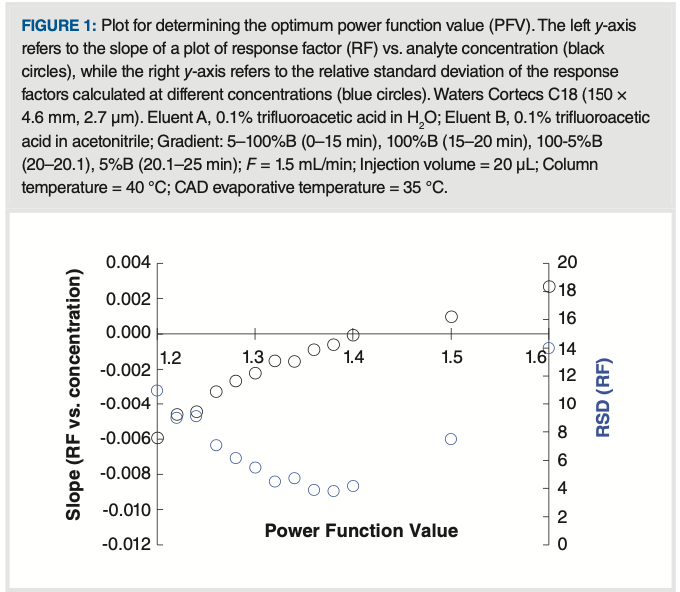
An alternative approach to expand the linear dynamic range of CAD is to transform the signal using a power function. Typically, a power function is implemented by raising the signal stream of the detector to a power n. This approach can yield highly linear plots of peak area vs. analyte concentration; however, in practice, it has been a challenge to determine the value of n (referred to hereafter as the power function value [PFV]) that yields the best quantitative performance in terms of accuracy and precision. The optimum PFV can be obtained by studying the variation in the detector response factor (RF = peak area/analyte concentration) with analyte concentration. Specifically, we can look at the slope of RF vs. analyte concentration, and the relative standard deviation (RSD) of RF values over the range of concentrations studied. If the PFV were to perfectly linearize the detector response, we would expect both the slope and RSD to be zero. Figure 1 shows experimental results from a study of the dependence of this slope and RSD on PFVs. We see that the optimum PFV in this case is about 1.4, corresponding to the lowest RSD value and a slope that is closest to zero.
FIGURE 1: Plot for determining the optimum power function value (PFV). The left y-axis refers to the slope of a plot of response factor (RF) vs. analyte concentration (black circles), while the right y-axis refers to the relative standard deviation of the response factors calculated at different concentrations (blue circles). Waters Cortecs C18 (150 × 4.6 mm, 2.7 μm). Eluent A, 0.1% trifluoroacetic acid in H2O; Eluent B, 0.1% trifluoroacetic acid in acetonitrile; Gradient: 5–100%B (0–15 min), 100%B (15–20 min), 100-5%B (20–20.1), 5%B (20.1–25 min); F = 1.5 mL/min; Injection volume = 20 μL; Column temperature = 40 oC; CAD evaporative temperature = 35 oC.

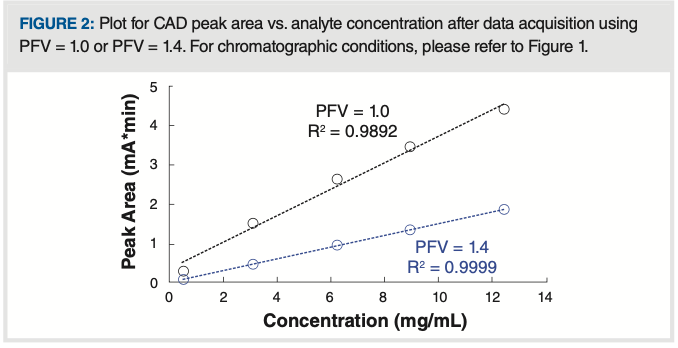
Figure 2 shows that, at the optimum PFV of 1.4, the relationship between peak area and analyte concentration is clearly more linear than when a PFV of 1.0 is used (that is, the default value in the software).
FIGURE 2: Plot for CAD peak area vs. analyte concentration after data acquisition using PFV = 1.0 or PFV = 1.4. For chromatographic conditions, please refer to Figure 1.

The conventional approach to obtain the optimum PFV involves acquiring peak areas for a standard at several concentrations, using several different PFVs, as shown in Figure 1. In our own work we have demonstrated the ability to predict the optimum PFV using only the CAD signal acquired with PFV = 1.0 (6). Recently, changes to commercially–available software for use with CAD have made determination of the optimum PFV much more user friendly.
Mobile Phase Considerations that Promote Success with CAD
As discussed above, a significant virtue of CAD is that it can “see” some compounds that are practically invisible to UV-absorbance detectors. The flipside of this characteristic of CAD, though, is that it will also “see” impurities in the mobile phase, or interferences in the sample, that would otherwise not be detected by UV-absorbance detectors if they do not contain chromophores. This is similar to the dilemma we often face with MS detection with electrospray ionization for LC separations—that it is exquisitely sensitive for detection of low concentration ionogenic compounds, but it is also very prone to detection of mobile-phase impurities that can give rise to high levels of detector back- ground. Given that CAD is most sensitive to nonvolatile compounds, the background signal in CAD is strongly affected by the concentration of nonvolatile impurities in the mobile phase. Therefore, many of the recommendations made regarding use of LC systems with MS detection and preparation of mobile phases for LC–MS also apply when using CAD. These are listed below:
1. When switching from the use of non-volatile buffers with UV-absorbance detection to volatile buffers and CAD, be sure to thoroughly flush (30–60 min) the LC system with the new, volatile buffers before connecting the CAD to the column outlet.
2. Use ultrapure water with low conductivity (18.2 MΩ∙cm and less than 5 ppb total organic carbon [TOC]) for mobile-phase preparation to minimize the concentration of non-volatile impurities. It is recommended to use fresh water rather than water stored in bottles because of the possibility of sodium leaching from glass.
3. Use high purity organic solvents to prepare the mobile phase to minimize the concentration of non-volatile impurities. We find that LC–MS-grade solvents are generally adequate.
4. Use volatile, low molecular weight acids and bases for buffer constituents (examples include, but are not limited to, formic acid, acetic acid, ammonium for- mate, and ammonium acetate).
5. Filter samples prior to analysis whenever large particulate matter may be present in the sample.
6. Use flow rates within the recommended range of the detector.
7. Adjust the evaporation temperature of the detector to ensure efficient and consistent nebulization for different mobile-phase conditions.
8. Choose chromatographic conditions (such as temperature, mobile phase pH, or organic solvent) that minimize the likelihood of stationary phase bleed from the column.
9. Avoid sources of contamination from glassware, filters, stir bars, pH electrodes, and laboratory equipment.
If a high background signal is observed, we recommend to start troubleshooting by removing the column while running LC–MS-grade mobile phase without additives. Once the background has returned to normal, the other components (buffer and column) can be added back one at a time while tracking the signal until the source of the higher-than-expected background is discovered.
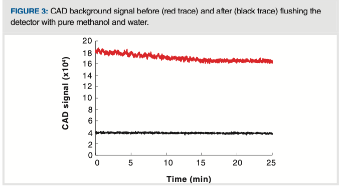
Figure 3 shows the impact on the CAD background signal of flushing the LC system and detector with high purity methanol and water after a period of use with buffered mobile phase. Comparing the background after flushing (black trace) to that before flushing (red trace), we see that there are decreases in short-term noise, magnitude of the background signal, and long-term drift of the signal.
FIGURE 3: CAD background signal before (red trace) and after (black trace) flushing the detector with pure methanol and water.

Summary
Many LC practitioners were trained using UV absorbance or MS detectors. Other detectors, including CAD and ELSD, which are attractive for the analysis of semi- and non-volatile compounds because they do not require that analytes have a light-absorbing chromophore, have increased in prominence in recent years. In this installment of “LC Troubleshooting,” we have highlighted some of the ways that CAD in particular is different from UV-absorbance detection, including nonlinear response to analyte concentration, and sensitivity to mobile-phase impurities. We hope that these tips are especially helpful for those new to CAD, and lead to development and implementation of successful methods involving this powerful detection technique.
References
(1) K. Zhang, K.L. Kurita, C. Venkatramani, and D. Russell, J. Pharm. Biomed. Anal. 162, 192–204 (2019) https://doi. org/10.1016/j.jpba.2018.09.029.
(2) K. Zhang and X. Liu, J. Pharm. Biomed. Anal. 128, 73–88 (2016). https://doi. org/10.1016/j.jpba.2016.05.007.
(3) J.P. Hutchinson, T. Remenyi, P. Nesterenko, W. Farrell, E. Groeber, R. Szucs, G. Dicinoski, and P.R. Haddad, Anal. Chim. Acta 750, 199–206 (2012). https://doi.org/10.1016/j. aca.2012.04.002.
(4) J. Tam, I.A.H. Ahmad, and A. Blasko, J. Pharm. Biomed. Anal. 155, 288–297 (2018). https://doi.org/10.1016/j.jpba.2018.03.067.
(5) P.H. Gamache, ed., Charged Aerosol Detection for Liquid Chromatography and Related Separation Techniques (John Wiley & Sons, Inc., Hoboken, New Jersey, 2017). https://doi. org/10.1002/9781119390725.
(6) I.A. Haidar Ahmad, A. Blasko, J. Tam, N. Variankaval, H.M. Halsey, R. Hartman, and E.L. Regalado, J. Chromatogr. A. 1603, 1–7 (2019). https://doi.org/10.1016/j.chroma.2019.04.017.
AUTHOR
Imad A. Haidar Ahmad is an Associate Principal Scientist and Supervisor in the Analytical Chemistry Enabling Technology group at Merck & Co., in Rahway, New Jersey, USA.
COLUMN EDITOR
Dwight R. Stoll is the editor of “LC Troubleshooting.” Stoll is a professor and the co-chair of chemistry at Gustavus Adolphus College in St. Peter, Minnesota, USA. His primary research focus is on the development of 2D-LC for both targeted and untargeted analyses. He has authored or coauthored more than 60 peer-reviewed publications and four book chapters in separation science and more than 100 conference presentations. He is also a member of LCGC’s editorial advisory board. Direct correspondence about this column to the Editor-in-Chief, Alasdair Matheson: amatheson@mjhlifesciences.com.

New Study Reviews Chromatography Methods for Flavonoid Analysis
April 21st 2025Flavonoids are widely used metabolites that carry out various functions in different industries, such as food and cosmetics. Detecting, separating, and quantifying them in fruit species can be a complicated process.
Extracting Estrogenic Hormones Using Rotating Disk and Modified Clays
April 14th 2025University of Caldas and University of Chile researchers extracted estrogenic hormones from wastewater samples using rotating disk sorption extraction. After extraction, the concentrated analytes were measured using liquid chromatography coupled with photodiode array detection (HPLC-PDA).

.png&w=3840&q=75)

.png&w=3840&q=75)


.png&w=3840&q=75)


.png&w=3840&q=75)


