In-Capillary Sample Concentration in CE
LCGC North America
Stacking and sweeping injection methods are compared and practical suggestions are provided about how to enhance sensitivity for charged and neutral compounds.
In this installment, guest authors and capillary electrophoresis (CE) experts Breadmore and Sänger-van de Griend bring a practical perspective to enhancing the sensitivity of CE. They compare stacking and sweeping injection methods and provide practical suggestions about how to enhance sensitivity for charged and neutral compounds.
One of the most frequently cited concerns in capillary electrophoresis (CE) is that the concentration limits of detection are inferior to what can be achieved with liquid chromatography (LC) (1). Extensive research has been carried out to overcome this limitation and now there are many different ways to increase sensitivity by controlling the way the sample is injected, how it is prepared, and how the targets are separated. After all, the concentration in the sample vial does not need to be the same as the concentration needed for detection if we can concentrate on-line. Early researchers in the field diluted samples in the electrolyte (parallel to dissolving or diluting in eluent in LC); however, doing so dilutes the target analytes, further reducing sensitivity. A better approach is to use the sample straight, which means that the composition of the sample plug is different from the composition of the electrolyte. Although intuitively this may not seem like a smart idea, depending on the exact analyte and conditions there may be a significant difference in their migration behavior in the sample zone compared to their migration behavior in the electrolyte. Very early researchers realized that this approach could enhance sensitivity. A brief search of the literature yields many excellent research papers and reviews (1–5), with different kinds of concentration mechanisms occurring because of different analyte, matrix, and electrolyte properties. Table I gives an overview of the most frequently used concentration techniques; as can be seen there are quite a number of them. It is worthwhile noting that these are the most common single concentration approaches used. It is possible to combine multiple mechanisms to produce even more powerful approaches; however, these are more complex. Most reviews discuss the various techniques from the mechanistic point of view. Here, we'd like to consider these options from a practical point of view and ask the question: I have XYZ in my sample; how do I improve my sensitivity? After all, in real life one usually cannot pick all conditions and sample matrices to suit a theoretically useful technique; instead, one has to work from the situation at hand.

Table I: In-capillary sample concentration in CE
Velocity Differences
First of all, the fundamental premise of concentration in CE comes back to creating a different velocity of the analytes of interest in the sample zone compared to their velocity in the background electrolyte (BGE) (6). There are many different techniques based on a change in velocity. Each technique has its own abbreviation, but the only difference may be a change in direction of the electroosmotic flow (EOF). These techniques fall into two groups: stacking techniques and sweeping techniques. If the velocity in the sample zone is higher than in the BGE (Figure 1b), the technique is generally called stacking (7). When stacking, the analytes quickly migrate through the sample zone to the electrolyte boundary where they slow down and "stack" together on the boundary with an increase in concentration and, thus, sensitivity (Figure 1b). In so-called sweeping techniques, in contrast, the velocity in the sample zone is slower than the velocity in the electrolyte. As the boundary between the electrolyte and sample moves through the sample matrix, analytes are concentrated around this moving boundary and are considered to be "swept" together with an increase in concentration and, thus, sensitivity (Figure 1c) (8).

Figure 1: Concentrating in CE. Creating velocity differences of the analyte in the sample zone versus the velocity of the analyte in the BGE. (a) Initial situation after injection and before applying the voltage. (b) Stacking, the analyte has a higher velocity in the sample zone than in the BGE. (c) Sweeping, the analyte has a lower velocity in the sample zone than in the BGE.
The Easiest Way: FASS
So if we want to create a concentrating effect inside the capillary, we have to ensure that the analyte has a difference in velocity between the sample zone and BGE. In an electric field, the velocity of an analyte is directly proportional to its electrophoretic mobility, which is governed by charge, size, and the electric field strength. This means that we need to know the analyte's physical-chemical properties. The first question in the decision process (see Figure 2) is as follows: Is the analyte charged? (And yes, whether the species is anionic or cationic is important, but only for determining the conditions to use when implementing the method; this does not matter when choosing the ideal approach for concentration.) If the analyte is neutral, then you need to use affinity approaches to achieve concentration, which are discussed later on.
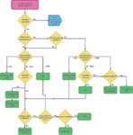
Figure 2: In-capillary sample concentration decision tree for charged analytes.
The second question is as follows: Does the sample matrix have a lower conductivity than the BGE? If yes, then field-amplified sample stacking (FASS) may well work (Figure 1b). This is the simplest approach because the lower conductivity of the sample zone automatically means that the field strength in the sample zone is higher than in the BGE. If the mobility of the analyte remains the same, then stacking will occur as a higher field strength results in a higher velocity without any other active manipulation (there is nothing you can do about it except to remove the conductivity difference). This is the reason that it is preferred to have the sample dissolved or diluted in something that has a lower conductivity than the BGE, including diluted BGE, pure water, or organic solvents. Ethanol, dimethyl sulfoxide (DMSO), and acetone can give even better results than pure water (9). As a consequence of the stacking effect, a larger volume than the usually mentioned 1% of the capillary volume can be injected. As a rule of thumb, injection volumes up to 5% of the total capillary volume are feasible with FASS, with enhancements in sensitivity typically less than about 50 achieved. Larger volumes do not produce further improvements because of mismatches in EOF, which causes hydrodynamic dispersion, a loss of efficiency (10,11), and decreased reliability because of the occurrence of bubbles.
When a Higher Concentration Is Needed
The sidebar "How Much Is Injected" provides some help in calculating the injected volumes or amounts. Sometimes a greater increase in concentration is required than can be achieved in FASS. This is easiest if the sample matrix has a controlled and constant composition. In such a case, field-amplified sample injection (FASI) (12) (also called field-enhanced sample injection [FESI]) and large-volume sample stacking (LVSS) can be easily used. The only difference between FASS and FASI is the injection — for FASI, electrokinetic injection is used. Because the amount injected is strongly dependent on the local field strength, the sample matrix conductivity should be constant. A variable sample matrix composition will result in variable amounts injected, which is why for all practical purposes FASI requires a controlled sample composition. The same is true for LVSS for similar reasons. In LVSS, the sample matrix is removed either through polarity switching (denoted LVSS) (10) or EOF pumping (denoted large-volume sample stacking with an EOF pump [LVSEP]) (13).
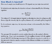
How Much Is Injected?
If the matrix varies, local field strengths vary and timing becomes an issue, resulting in variable concentration effects and migration times. To some extent these problems can be compensated for with an internal standard, but method performance (detection limit, repeatability, and so on) will be compromised so it is better to address the cause of the problem, rather than doing a patch-up job with duct tape and silly putty.
If the matrix composition is variable, we first look again at the analyte: Is it a weak base or acid? If yes, stacking with a dynamic pH junction (6,14), also called a moving neutralization boundary (15), is feasible. Here, the BGE and sample composition are selected such that there is a difference in charge, because a charge difference will also result in different velocities between the sample and BGE zone. It is important to note that it is not necessary to completely reverse the charge; a simple change from charged to neutral may be sufficient if the system is designed correctly. If the answer is no, sweeping techniques may be appropriate. In sweeping, analyte affinity for a pseudo-stationary phase (PSP) is key. When the PSP migrates through the sample zone, analyte molecules are concentrated at the front of the PSP as it moves through the sample zone (Figure 1c) (8). If the PSP is a part of the BGE, such as in micellar electrokinetic chromatography (MEKC), it is called sweeping. If the PSP is in the sample and the BGE is PSP-free, then when the micelles migrate into a PSP-free zone, the concentration of the surfactant reduces to below the critical micelle concentration and the micelles collapse, releasing the analytes. This was first introduced for neutral species as analyte focusing by micelle collapse (AFMC), but has been applied to charged species with organic solvents to collapse the micelles and is then called micelle to solvent stacking (MSS). It is important to note that the mechanism of sweeping and MSS still function with a variable matrix, but there may be some resultant variability in the final separation. Nevertheless, similar to isotachophoresis (ITP), discussed below, these approaches are very useful for samples with a variable matrix.
High-Conductivity Sample Matrix
If the sample matrix has a high conductivity, it is important to consider off-line cleanup. From the discussion above and from the decision tree (Figure 2), it can be seen that with a lower conducting sample matrix, many approaches can be used for successful sensitivity enhancement. If the sample matrix has a high level of conductivity but off-line cleanup is not feasible, there are some options available. These are based on creating velocity differences by sweeping or MSS, by manipulating the charge by pH-mediated techniques (such as pH-mediated FASS or dynamic pH junction), or by ITP. Of these, pH-mediated FASS is an interesting and unique approach that induces a FASS effect in an indirect manner (16). In this approach, sample is injected electrokinetically, and for anions, the electrolyte would contain a weak base, like ammonium, such that during injection the anions migrate into a zone where the counterion is ammonium (not sodium as it may have been in the sample). After injection of the sample, there is a short electrokinetic injection of base (or acid for cations). The base migrates into the sample zone (hydroxide and hydronium have a high mobility) and titrates the buffer counterion into water, thereby producing neutral species and reducing the conductivity of the sample zone. With this change in conductivity, there is now a higher electric field over the sample and FASS can occur. Although this is a very clever approach, it is not easy to optimize the conditions to achieve the outcome required.
Transient ITP
Perhaps the most attractive approach for charged species in samples with a high conductivity matrix is to use isotachophoresis (ITP) (Figure 3). ITP is one of the oldest forms of CE and probably the most intimidating — and also poorly understood by many experienced practioners of CE. In ITP, the sample is sandwiched between a leading electrolyte and a terminating electrolyte. The leading electrolyte has an ion with the same charge as the analyte but with a higher mobility. The terminating electrolyte has an ion with the same charge as the analyte but a lower mobility. The sample analytes sort in migration order and are concentrated to obtain the same conductivity in each analyte zone. The mobility and concentration of the leading electrolyte determine the concentrating effect on the analytes, according to the Kohlrausch regulation function, and the mobility window between the leading and terminating ions provides a zone in which the analyte range can be selectively tuned. The unique mechanism of ITP makes it the great equalizer. Macrocomponents are diluted and trace components are concentrated, making ITP exceptionally useful as a stacking technique.
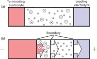
Figure 3: Isotachophoresis (ITP), (a) initial conditions with injection of sample between the leading and terminating electrolytes, (b) isotachophoretic zones at steady state.
The simplest way to use ITP is to perform transient ITP (tITP) (17). Here, a short ITP stage is induced before the CE separation. Transient ITP can be done by injecting small volumes of leading and terminating electrolytes on either side of the sample; alternatively, either the leading or termination co-ion comes from the BGE (not both) and the other comes from the sample or from an additionally injected plug. Transient ITP is particularly suited to salty samples — especially those that contain lots of sodium chloride as the chloride is a very high mobility ion that can function as a leader for almost all anions. Sodium is a mid-range mobility cation so it cannot be used for all cations, but it typically has a higher mobility than many organic cations. It is also worth briefly mentioning pseudo-ITP (pITP), in which the terminating zone is created not from a low mobility ion, but from a solvent added to the sample in which there is a lower conductivity (18). This approach arose out of work where the supernatant of biological samples after deproteination with acetonitrile was injected into the CE, and it is therefore a very useful technique for plasma and serum samples because they require very simple sample processing.
The Last Resort: In-Capillary and In-Vial Extraction
If stacking and sweeping approaches do not work, then the only real alternative is to consider the use of an on-line or in-capillary extraction. Such extractions have traditionally been performed by making a small chromatographic bed (19) at the tip of the capillary (most easily done with larger-internal-diameter tubing and particles that have a larger diameter than the internal diameter of the separation capillary) and allowing analytes to be extracted chromatographically before electrophoretic separation. The technique resembles on-line solid-phase extraction (SPE) and includes possibilities for immunoaffinity extraction as well (20). While this is a potentially very attractive approach, there are a number of limitations including analysis time, repeatability, and the lack of commercially available capillaries. Therefore, it is really only useful for researchers.
The most common off-line alternative to SPE is liquid–liquid extraction (LLE) (21), which has only very recently been reported coupled directly with CE through developments in single-drop microextraction (SDME). Small individual drops of organic and organic–aqueous drops can be created on the tip of the capillary in a commercial CE unit (22). This allows for easy automation, with very good analytical performance; however, this is not a straightforward approach at this point in time because a slight back pressure is required to stabilize the drop. A more attractive approach is the implementation of the technique in a vial. This can be done with a water-immiscible ionic liquid (23), and excellent results have been obtained from urine and serum; this is an area very much still in its infancy, and it is unclear yet whether this technique will be attractive. The most promising approach to appear recently is the development of in-vial supported liquid membranes (SLM) (24) and electromembrane extraction (EME) (25). Still very much in the research phase, these techniques involve creating a custom vial in which the sample is placed below a membrane impregnated with a suitable extraction solvent with an aqueous acceptor phase placed on top of the membrane. When placed in a commercial CE system, the capillary samples directly from the surface of the membrane, which considerably decreases the time required to reach localized equilibrium (26). This approach has been demonstrated for inorganic ions and a few drugs from various biological fluids. If it can be transitioned into a commercial vial, it will significantly aid the ability of CE to easily handle complex and high conductivity samples.
How to Deal with Neutral Species
The options for uncharged analytes are fewer than those for charged analytes. For uncharged analytes, all in-capillary approaches are based on some kind of affinity interaction (27). This is because neutral species are uncharged and do not have their own electrophoretic mobility and, thus, cannot be concentrated by approaches developed for charged compounds. In contrast, many of the approaches developed for neutral analytes can also be applied to charged analytes and some were already discussed in detail above. Figure 4 shows the decision tree for uncharged analytes.
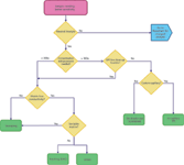
Figure 4: In-capillary sample concentration decision tree for neutral analytes.
The first approaches to concentrate neutral species were based on stacking: By using a low conductivity sample and affinity between the analyte and a PSP, it is possible to rapidly transport analyte molecules from the sample zone to the sample or electrolyte boundary where they concentrate. There is an abundance of slightly different approaches here depending on the direction of the micelle and the polarity, but they all rely on stacking (not sweeping) for concentration (27).
Today, however, the method of choice for concentrating neutral analytes is sweeping as this can provide greater enhancements than stacking and is applicable to samples with a low, high, or variable sample matrix (8,28). The challenge with sweeping is that for good enhancement a high affinity with the PSP is required (the zone length after sweeping is related to the affinity interaction), but this approach is bad for separation as all of the analytes will migrate with the PSP. Therefore, sweeping requires careful optimization to ensure that sufficient sensitivity enhancements can be obtained. Sweeping is also attractive because it is applicable to high conductivity samples — the mechanism of concentration does not depend on the conductivity of the sample. In fact, when sweeping is combined with electrokinetic injection, multiple capillary volumes of sample can be injected by the EOF with the analytes concentrated and held at the front of the micelle zone (29). This approach can provide very significant enhancements, but the trade-off is time — typically, very long injections (approaching an hour) are required.
The Chicken or the Egg — Which Part of Your Method to Consider First
The typical approach used by most workers in the field is to develop separation conditions to resolve the target analytes from matrix components, and to then consider whether or not any on-line concentration techniques can be used. The justification here is twofold; it doesn't really matter what sensitivity you have if you can't separate the analytes (with increased prevalence of mass spectrometers this may become arguable) and you can always resort to off-line treatment of your sample to improve the sensitivity. This latter point in particular is worth some consideration because it is not easy, for example, to concentrate by more than 100 — this is the equivalent of taking 10 mL of sample, and extracting the analytes into a volume of 100 μL. A volume of less than 100 μL can be difficult to handle and introduces other errors. Stacking and sweeping approaches are getting closer to being able to electrokinetically extract from 100 μL into 1–5 nL (100,000-fold), but this is only possible for certain sample types and is only possible if the separation method is compatible with these approaches.
You don't need a chicken or an egg — you need both. Therefore, it would be prudent to consider the requirements of sensitivity during method development and ensure that the developed method is compatible with at least some of the concentration approaches. For example, if you know that you will need nanogram-per-liter detection limits or lower, then that really does place restrictions on the concentration approaches that can be used and implicates which methods you need to use. This, in turn, defines the electrolyte compositions that may be more ideal and compatible.
Other Practical Limitations: pH, pI, Stability, and Analyte Size
In the discussion of sensitivity enhancement so far, we have not indicated whether any technique is typically more or less suitable for a certain class of molecules, other than via physicochemical properties like weak acid and bases, charged or uncharged analytes, and high or low affinity for a pseudo-stationary phase. This is deliberate because it is the physicochemical properties that govern which method is suitable. A dynamic pH junction (essentially a step pH gradient) is useful for proteins with an isoelectric point (pI) between the pH of the sample and the electrolyte, not because of size, but because of their pI values. Of course there are other practical limitations that need to be considered for all molecules, but have some greater relevance for larger molecules. Knowledge about other parameters such as stability or adsorption should always be included in the decision process. Limiting for all concentration efforts is the solubility of the analyte — low solubility situations should be avoided (such as proteins at their pI) unless a solubility-enhancing solvent or compound is added. The sidebar "Good CE Injection Practice" lists some other practical tips to improve method performance.
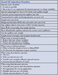
Good CE Injection Practice
What's Good for the Goose, Isn't Always Good for the Gander
As can be understood from the discussions above, opportunities for sensitivity enhancement through injection are strongly influenced by other method parameters, such as the BGE composition. A higher BGE concentration, for example, makes it easier to increase the conductivity difference with the sample, but this causes higher currents, which may lead to greater method instability. Although very high sensitivity enhancements have been published with stacking techniques, in the end it always comes down to compromising between robustness and resolution (that is, separation plus efficiency) versus sensitivity. Depending on the required use one has to make choices and take the consequences.
Stacking or Sweeping — Or Both?
The right in-capillary sample concentration method to use with CE depends on the properties of the analytes. With a target set of analytes with diverse properties, finding a suitable method can be complex. An example of this is shown in Figure 5. This is a mixture of eight hypolipidemics with a diverse range of properties including mobility, pKa, and lipophilicity. This latter property is a problem because pravastatin, gemfibrozil, and rosuvastatin show poor interaction with the PSP and thus are not swept well. The solution in this case was to perform sweeping under FASS conditions — sweeping the high lipophilic analytes and stacking the low lipophilic ones. The enhancements are modest (40–80-fold) but this nevertheless shows the potential of using multiple mechanisms simultaneously to improve analyte coverage. This is different than using sequential approaches such as dynamic pH junction–sweeping, which uses one method to concentrate and then a second method to sharpen the peaks further and improve efficiency. These combined approaches are more complex and beyond the scope of the article, but there really is no limit to the combinations of methods that can be used.

Figure 5: Sweeping and FASS plus sweeping of standard mixture of hypolipidemic drugs. Capillary: 78 cm à 50 μm LPA-coated capillary; BGE: 20 mM ammonium bicarbonate (pH 8.50) containing 50 mM SDS; voltage: -28 kV. Sweeping: hydrodynamic injection of 10 μg/mL drug mixture in ammonium bicarbonate with conductivity similar to BGE at 50 mbar for 40 s. FASS plus sweeping: hydrodynamic injection of 1 μg/mL drug mixture in Milli-Q water at 50 mbar for 80 s. Peaks: A = atorvastatin, F = fluvastatin, G = gemfibrozil, L = lovastatin, M = mevastatin, P = pravastatin, R = rosuvastatin, S = simvastatin. Adapted from reference 30 with permission from Elsevier.
The Final Word
The right approach to sample concentration for CE is one that will meet your needs. Determining this isn't a simple matter, and in many cases there may be more than one possible approach that would be suitable. Literature can be useful to identify what may be more appropriate, but ultimately it will come down to experimenting until the appropriate conditions are found. The best advice is to start with a simple approach and only add complexity if it is absolutely needed.
Acknowledgment
The sidebar "Good CE Injection Practice" was reproduced with permission, Cari Sänger, CESolutions 5. Injection precision and sensitivity, Separation Science, http://www.sepscience.com/Techniques/CE/1352-/CE-Solutions-5-Injection-Precision-and-Sensitivity.
References
(1) M.C. Breadmore, J. Chromatogr. A 1221, 42–55 (2012).
(2) A. Slampova, Z. Mala, P. Pantuckova, P. Gebauer, and P. Bocek, Electrophoresis 34, 3–18 (2013).
(3) M.C. Breadmore, A.I. Shallan, H.R. Rabanes, D. Gstoettenmayr, A. Syazwani Abdul Keyon, A. Gaspar, M. Dawod, and J.P. Quirino, Electrophoresis 34, 29–54 (2013).
(4) F. Kitagawa and K. Otsuka, J. Chromatogr. A (2013), http://dx.doi.org/10.1016/j.chroma.2013.10.066.
(5) Y. Wen, J. Li, J. Ma, and L. Chen, Electrophoresis 33, 2933–2952 (2012).
(6) P. Britz-McKibbin, G.M. Bebault, and D.D.Y. Chen, Anal. Chem. 72, 1729–1735 (2000).
(7) R.-L. Chien and D.S. Burgi, Anal. Chem. 64, 489A–496A (1992).
(8) J.P. Quirino and S. Terabe, Anal. Chem. 71, 1638–1644 (1999).
(9) Z.K Shihabi, J. Chromatogr. A 1066, 205–210 (2005).
(10) R.-L. Chien and D.S. Burgi, Anal. Chem. 64, 1046–1050 (1992).
(11) C. Huhn and U. Pyell, J. Chromatogr. A 1217, 4476–4486 (2010).
(12) R.-L. Chien and D.S. Burgi, J. Chromatogr. 559, 141–152 (1991).
(13) Y. He and H.K. Lee, Anal. Chem. 71, 995–1001 (1999).
(14) P. Britz-McKibbin and D.D.Y. Chen, Anal. Chem. 72, 1242–1252 (2000).
(15) C.-X Cao, L.-Y. Fan, and W. Zhang, Analyst 133, 1139–1157 (2008).
(16) S. Park and C.E. Lunte, J. Microcol. Sep. 10, 511–517 (1998).
(17) F. Foret, E. Szoko, and B.L. Karger, J. Chromatogr. 608, 3–12 (1992).
(18) Z.K. Shihabi, J. Chromatogr. 652, 471–475 (1993).
(19) R. Ramautar, G.W. Somsen, and G.J. de Jong, Electrophoresis 35, 128–137 (2014).
(20) N.A. Guzman, T. Blanc, and T.M. Phillips, Electrophoresis 29, 3259–3278 (2008).
(21) S. Pedersen-Bjergaard and K.E. Rasmussen, Anal. Chem. 71, 2650–2656 (1999).
(22) K. Choi, J.K. Su, G.J. Yoo, O.J. Yong, J.S. Kim, and S.C. Doo, Anal. Chem. 81, 225–230 (2009).
(23) M.C. Breadmore, J. Chromatogr. A 1218, 1347–1352 (2011).
(24) S. Pálmarsdóttir, E. Thordarson, L.E. Edholm, J.Å. Jönsson, and L. Mathiasson, Anal. Chem. 69, 1732–1737 (1997).
(25) S. Pedersen-Bjergaard and K.E. Rasmussen, J. Chromatogr. A 1109, 183–190 (2006).
(26) P. Pantůčková, P. Kubáň, and P. Boček, J. Chromatogr. A 1299, 33–39 (2013).
(27) A.T. Aranas, A.M. Guidote, Jr., and J.P. Quirino, Anal. Bioanal. Chem. 394, 175–185 (2009).
(28) J.P. Quirino and S. Terabe, Science 282, 465–468 (1998).
(29) J. Palmer, N.J. Munro, and J.P. Landers, Anal. Chem. 71, 1679–1687 (1999).
(30) M. Dawod, M.C. Breadmore et al., J Chromatogr A 1217, 386–393 (2010).
Michael C. Breadmore is an ARC Future Fellow (2013–2017) at the Australian Centre for Research on Separation Science (ACROSS) based at the University of Tasmania. His research interests lie in the application of capillary and microchip electrophoresis to the trace analysis of environmental, clinical, and forensic samples, as well as in methods for the low-cost fabrication of microfluidic devices.

Michael C. Breadmore
Cari E. Sänger-van de Griend is a consultant and trainer at Kantisto BV, a pharmaceutical analytical consultancy she founded after 20 years in industry. She is a globally recognized expert on the implementation of CE techniques and a specialist on pharmaceutical analysis. She is also an Associate Professor in Analytical Pharmaceutical Chemistry at Uppsala University in Sweden and an Adjunct Senior Lecturer at the Australian Centre for Research on Separation Science (ACROSS), University of Tasmania.

Cari E. Sänger-van de Griend
The editor of Column Watch:
Ronald E. Majors "Column Watch" Editor Ronald E. Majors is an analytical consultant and is a member of LCGC's editorial advisory board. Direct correspondence about this column to lcgcedit@lcgcmag.com.

Ronald E. Majors

Perspectives in Hydrophobic Interaction Temperature- Responsive Liquid Chromatography (TRLC)
TRLC can obtain separations similar to those of reversed-phase LC while using only water as the mobile phase.

.png&w=3840&q=75)

.png&w=3840&q=75)


.png&w=3840&q=75)


.png&w=3840&q=75)


