But Why Doesn’t It Get Better? Kinetic Plots for Liquid Chromatography, Part 3: Pulling It All Together
In the last two instalments of “LC Troubleshooting”, we reviewed the basic idea of a “kinetic plot” (1) and how to make the plots from experimental data or data from the literature (2). Ultimately, this graphical tool can be used to make informed decisions when choosing columns and to understand why a column might not be delivering expected performance improvements. This month, we conclude this series of articles by discussing the so-called “Knox-Saleem limit” (KSL), application of kinetic plots to gradient elution conditions, and the impact of extracolumn dispersion on kinetic plots. Finally, we introduce a web-based application that pulls together all of the theory discussed in these instalments into a convenient and flexible web‑based calculator that allows you to explore the impact of many variables on the kinetic plot on your own.
The Knox-Saleem Limit (KSL)
In last month’s instalment, we began discussing the effect of particle size on kinetic plots by showing the kinetic performance limit (KPL) curves for different particle sizes (Figure 1[a]). Interestingly, these curves cross in the kinetic plot, which means that at any given combination of t0 and N, there is one particle size that provides superior performance compared to the others. In other words, there is no single particle size that is superior to all others over the entire range of analysis times of practical interest. Whereas the smallest particles (1.7 µm) show the best kinetic performance at short analysis times, the larger particles (5 µm) are the better choice to obtain high efficiencies at long analysis times, which is a direct result of the improved performance at higher flow rates for smaller particles (fast analysis). However, the small particles also lead to large pressure drops that limit their use to relatively short columns (lower efficiency).
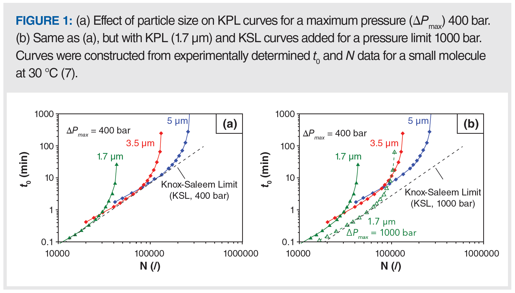
In Figure 1(a), we see that each of the KPL curves touches an oblique asymptote (dashed lines) below which one cannot work regardless of the choice of column length, particle size, and velocity because the pressure drop will exceed the chosen pressure limit. This oblique asymptote is the KSL and in fact touches the KPLs for different particle sizes at their respective optimal mobile phase velocities (that is, u0,min) (3). The point where the KPL and KSL curves touch represents the optimal choice of not only mobile phase velocity and column length but also of the particle size for each combination of t0 and N. For the particle sizes represented in Figure 1, we see that the KPL curves come very close to the KSL, which indicates that at least one of these particles is close to optimal for plate numbers in the range of 10,000 < N < 200,000. When there is a gap in the available particles sizes (for example, jumping from 1.7 to 3.5 µm), we see a gap between the points at which the two KPL curves cross with the KSL. This occurrence indicates a gap between the truly optimal performance that is possible for a given combination of t0 and N, and what can actually be realized with the available particle sizes. Fortunately, these differences are rather small, as has been discussed in detail by Matula and Carr in the literature (4).
The KSL can be calculated using equation 1 if the dynamic viscosity of the mobile phase (η), the minimum reduced plate height (hmin), and the u0‑velocity-based flow resistance (Φ0) for a certain stationary phase support are known using (2,3,5):

This relationship makes clear that the kinetic performance can be improved by increasing the maximum operating pressure (ΔPmax; that is, ultrahigh-pressure liquid chromatography [UHPLC] vs. high performance liquid chromatography [HPLC]), decreasing the mobile phase viscosity (for example, through the use of high temperatures in LC, or low viscosity eluents in supercritical fluid chromatography [SFC]), reducing the flow resistance (for example, by using monolithic or chip-based columns), or decreasing the minimum reduced plate height (for example, with superficially porous particles, chip-based, or 3D-printed columns) (6). A change in any of these parameters will shift the KSL (and also the KPL curves) to the right, allowing for both faster and more efficient separations. When all other parameters are fixed, doubling ΔPmax results in a decrease in t0 by a factor of two. In other words, doubling the available pressure allows the same efficiency to be realized in half the time, which is illustrated in Figure 1(b) where the effect of the operating pressure on the KPL curve for the 1.7 µm particles is shown (7). The curve shifts to the bottom right of the kinetic plot, showing how even faster analyses and higher efficiencies can be obtained when operating at this higher maximum pressure. In fact, when comparing the use of 1.7 µm particles at 1000 bar with 3.5 and 5 µm particles used at 400 bar, the smaller 1.7 µm particles outperform the 3.5 µm particles in the part of the efficiency analysis time range where the latter outperforms the 5 µm particles at 400 bar. The 1.7 µm particles at 1000 bar even outperform the 5 µm particles up to approximately N ~100,000. Of course, this comparison changes if the 3.5 and 5 µm particles can also be used at 1000 bar. Similarly to the KPL curve, the KSL also shifts with an increase in maximum pressure, as expected from equation 1.
Application of the Kinetic Plot Concept to Gradient Elution Conditions
For fundamental comparisons of the separation performance of different column types, it is most practical to use isocratic elution conditions, which is why our discussion of kinetic plots has so far focused on the kinetic plots with t0 and N as the axes. In practice, however, most applications use mobile phase composition gradients to optimize separation time and resolution. Thus, it is desirable to apply the kinetic plot concept to the gradient elution condition as well, which can be done by replacing the plate number with the peak capacity (np) as the measure of separation performance (5,8). When making experimental measurements of retention time and peak width under gradient elution conditions for the purpose of making kinetic plots from experimental data, several details are important to keep in mind. These are mentioned briefly here. Readers interested in learning more about them are referred to the literature for detailed protocols (9).
Gradient time should be scaled inversely proportional to the flow rate so that the gradient slope remains constant (10,11).
If the mobile phase composition is held constant at the beginning of the separation, or at any other point in the elution program, these so-called hold times should also be scaled with the inverse of the flow rate.
If columns with the same stationary phase chemistry from the same vendor are compared, there is usually little to no difference in selectivity and the same gradient range (initial and final composition) can be used. However, when comparing columns from different vendors, differences in retention may be observed, and it is advisable to tune the initial and final composition of the gradient in such a way that the first and last eluted compounds have similar retention factors (9,11).
As previously mentioned, in the case of gradient elution, the peak capacity (np) is usually the preferred measure of separation performance rather than the column plate count (N). Calculation of the column dead time and retention time at the kinetic performance limit (that is, t0,KPL, and tR,KPL) is similar in isocratic and gradient elution, however calculation of the peak capacity at the KPL is slightly different, as shown in equations 2 and 3 (9,10,12,13):
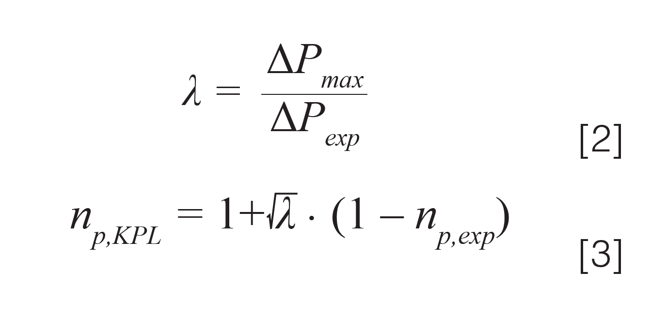
The square root dependence in equation 3 is the direct result of the square root dependence of the peak capacity on the column plate number (10). As a result, increasing the column length by a factor of four will only increase the peak capacity by a factor of two. Please note that also in this case the value for ΔPexp should include the extracolumn pressure drop as discussed in the next section.
Effects of Extracolumn Dispersion on Kinetic Plots
So far in this series, we have not discussed the impact of extracolumn dispersion (ECD) on kinetic plots, which is mathematically convenient. However, peak dispersion outside of the column is often too large to ignore. We discussed the details associated with dispersion in different parts of the LC system in a prior multipart series of articles in this magazine (14–17) and elsewhere (18), and readers interested in these details are referred there. Here, we focus on adjustments that must be made to the kinetic plot calculations to account for both the dispersion that occurs in the LC system outside of the column, and the pressure drop that occurs in different parts of the system.
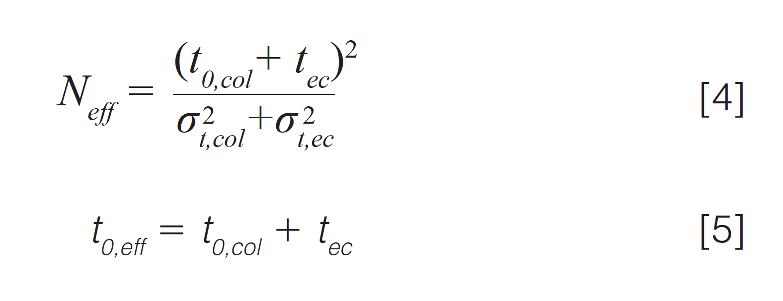
Corrections to the kinetic plot calculations to account for extracolumn effects can be made using values for the extracolumn dispersion and pressure drop obtained from experiments, or some means of estimation. When it comes to experimental measurements, the column is replaced by a zero dead volume union in order to obtain the extracolumn time (tec) and peak variance (σ2t,ec) at different flow rates. It is important to understand that extrapolation of the plate number from a FL curve to the KPL using λ = ΔPmax/ ΔPexp (as discussed in Part 2 of this series) should only be done using plate numbers that have been corrected for ECD. Then, after the extrapolation, the extracolumn variance is added back to the peak variance contributed by the column to give an effective plate number (Neff) as shown in equation 4. Similarly, the column dead time must be corrected to account for the time the analyte spends travelling from the injector to detector, but outside of the column, as shown in equation 5:
In addition to the effect of the LC system on dispersion of peaks, some of the available operating pressure is also lost because of pressure drops along the connecting tubes, especially when narrow diameter tubes are used. To account for this, the value of ΔPmax used in calculating the kinetic curves should be reduced by the value of the extracolumn pressure drop (ΔPec) at the corresponding flow rate, as shown in equation 6:

Pulling It All Together—A Web‑Based Application for You
Although no single mathematical step in calculating the kinetic curves is particularly difficult, there are many details to keep track of, and building a calculator correctly from scratch takes some time. Thus, we have built a freely available web-based calculator (www.multidlc.org/kinetic_plot_tool) that incorporates all of the theory discussed in this series of articles, including consideration of extracolumn effects discussed in the previous section. Here, we briefly demonstrate use of the tool by way of an example that shows how it can be used to explore the effects of different variables on the curves, and perhaps develop hypotheses for troubleshooting situations where column performance does not live up to one’s expectations.
Figures 2 and 3 show screenshots of the inputs to the tool. Up to three different conditions can be compared simultaneously. Pre-set configurations for zero, low (~1–2 µL2), and normal (~10–15 µL2) levels of extracolumn dispersion enable quick configuration of the extracolumn inputs; however, each of the system parameters (that is, injector, tubing, and detector) are fully adjustable as well.
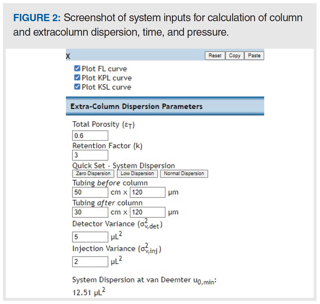
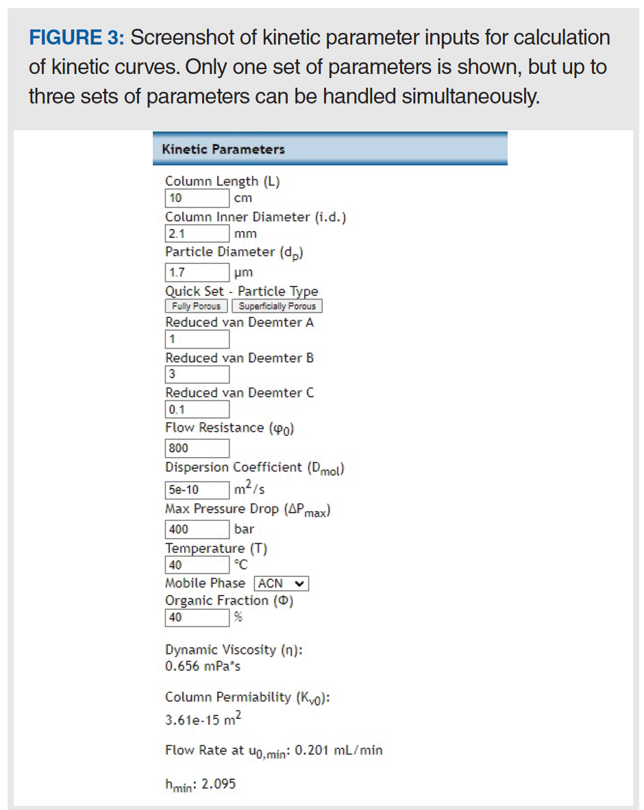
Figure 4 shows screenshots of the kinetic plots produced by the tool for two different cases (A and B). In both cases the comparison is between columns packed with fully porous 1.7 µm particles and columns packed with superficially porous 2.7 µm particles. In case A, the tool is configured using the pre-set parameters for a low dispersion system (~1–2 µL2) for both the FPP and SPP columns. Here, we see that the 1.7 µm FPP columns outperform the 2.7 µm SPP ones at the KPL over the range of 5000 < N < 30,000, though the difference is small (t0,FPP = 0.28 min vs. t0,SPP = 0.31 min for 15,000 plates). At approximately N = 30,000 plates, the curves cross over and the SPP columns become superior for higher efficiencies as a result of their higher permeability.
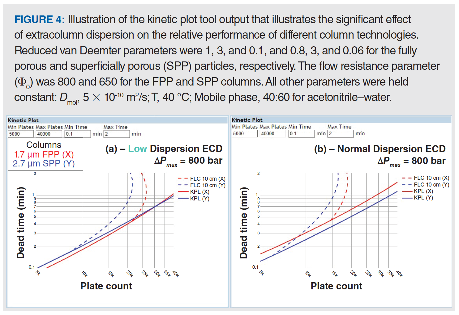
However, when the tool is reconfigured using the preset parameters for a normal dispersion system (~10–15 µL2), we get the curves shown in Figure 4(b), where the SPP columns are superior to the FPP ones at the KPL over the entire range of efficiencies shown. On one hand, the superiority of SPP columns is not surprising: manufacturers of sub-2-µm columns have been working to educate users for years about the importance of using these columns in low dispersion systems to maximize their performance potential. On the other hand, this comparison shows the utility of the kinetic plot tool, both for making informed choices about column selection and troubleshooting situations where a column in use does not live up to user expectations.
Summary
In this instalment of “LC Troubleshooting”, we have continued our discussion of kinetic plots and their utility when selecting column technologies and formats, and troubleshooting columns that appear to not live up to our expectations. The KSL quantifies the best achievable performance (as measured by plate number) in a given analysis time when the particle size is allowed to vary. Kinetic plots can also be used to compare technologies under gradient elution conditions, and when the effects of extracolumn dispersion are accounted for. Finally, we have introduced a freely available web‑based kinetic plot tool that leverages all of the theory discussed in this series and enables comparison of up to three different sets of conditions simultaneously. This tool is useful for quickly comparing different column technologies and LC system configurations, and developing troubleshooting hypotheses when things don’t seem to be quite right. It is important to note that all calculations in this series have been done with diffusion coefficients typical of small molecules. When working with large molecules their diffusion coefficients will be very different, and thus the kinetic plots will be very different as well.
References
- K. Broeckhoven and D.R. Stoll, LCGC Europe 35(2), 52–56 (2022).
- K. Broeckhoven and D.R. Stoll, LCGC Europe 35(3), 93–97 (2022).
- J.H. Knox and M. Saleem, J. Chromatogr. Sci. 7, 614–622 (1969).
- A.J. Matula and P.W. Carr, Anal. Chem. 87, 6578–6583 (2015).
- G. Desmet, D. Cabooter, and K. Broeckhoven, Anal. Chem. 87, 8593–8602 (2015).
- K. Broeckhoven and G. Desmet, Anal. Chem. 93, 257–272 (2021).
- Y. Vanderheyden, D. Cabooter, G. Desmet, and K. Broeckhoven, J. Chromatogr. A 1312, 80–86 (2013).
- X. Wang, D.R. Stoll, P.W. Carr, and P.J. Schoenmakers, J. Chromatogr. A 1125, 177–181 (2006).
- K. Broeckhoven, D. Cabooter, S. Eeltink, and G. Desmet, J. Chromatogr. A 1228, 20–30 (2012).
- K. Broeckhoven, D. Cabooter, F. Lynen, P. Sandra, and G. Desmet, J. Chromatogr. A. 1217, 2787–2795 (2010).
- K. Broeckhoven, D. Cabooter, and G. Desmet, LCGC Europe 24, 396–404 (2011).
- K. Broeckhoven and G. Desmet, J. Sep. Sci. 44, 323–339 (2021).
- T.J. Causon, K. Broeckhoven, E.F. Hilder, R.A. Shellie, G. Desmet, and S. Eeltink, J. Sep. Sci. 34, 877–887 (2011).
- D.R. Stoll, T.J. Lauer, and K. Broeckhoven, LCGC Europe 34(11), 464–469 (2021).
- D.R. Stoll and K. Broeckhoven, LCGC Europe 34(7), 277–280 (2021).
- D.R. Stoll and K. Broeckhoven, LCGC Europe 34(6), 232–237 (2021).
- D.R. Stoll and K. Broeckhoven, LCGC Europe 34(5), 181–188 (2021).
- G. Desmet and K. Broeckhoven, TrAC Trends in Anal. Chem. 119, 115619 (2019).
About The Authors
Ken Broeckhoven is Associate Professor at the Vrije Universiteit Brussel (VUB), in Brussels, Belgium.
Caden Gunnarson is currently a student and a researcher in the Stoll laboratory at Gustavus Adolphus College in St. Peter, Minnesota, USA.
About The Column Editor
Dwight R. Stoll is the editor of “LC Troubleshooting”. Stoll is a professor and the co-chair of chemistry at Gustavus Adolphus College in St. Peter, Minnesota. Direct correspondence to: amatheson@mjhlifesciences.com

Determining the Effectiveness and Safety of Cinnamon Derivatives for Diabetes Treatment with HPLC
March 27th 2025Cinnamon and its byproducts have been used for many years because of their antidiabetic effect. In a joint study conducted by Gazi University (Ankara, Turkey) and Düzce University (Düzce, Turkey), high performance liquid chromatographic (HPLC) and thin-layer chromatography (TLC) analyses, macroscopic analyses, and enzyme inhibition assays on diabetes-related enzymes were performed on cinnamon samples to determine whether they are safe to use for health purposes.


