What’s the Most Meaningful Standard for Mass Spectrometry: Instrument Detection Limit or Signal-to-Noise Ratio?
Special Issues
When evaluating the performance of mass spectrometers, one needs to consider the best (or most meaningful) figure of merit to use; options include instrument detection limit (IDL) and signal-to-noise ratio (S/N). In the last 15 years, vendor specifications for S/N have increased from 10:1 to greater than 100,000:1. Does that accurately reflect improvements in mass spectrometers? Although there have been many significant changes, the change in S/N specifications has been far greater than the corresponding change in method detection limits (MDL). Under appropriate conditions, S/N is a meaningful standard, but the value of any S/N must be evaluated in context of the chromatography and sample. Factors influencing the validity of vendor S/N specifications are reviewed, and the statistical alternative of IDL is presented as a replacement that is more consistent with regulatory guidelines and a more relevant indicator of instrument performance.
When evaluating the performance of mass spectrometers, one needs to consider the best (or most meaningful) figure of merit to use; options include instrument detection limit (IDL) and signal-to-noise ratio (SNR). In the last 15 years, vendor specifications for SNR have increased from 10:1 to greater than 100,000:1. Does that accurately reflect improvements in mass spectrometers? Although there have been many significant changes, the change in SNR specifications has been far greater than the corresponding change in method detection limits (MDL). Under appropriate conditions, SNR is a meaningful standard, but the value of any SNR must be evaluated in context of the chromatography and sample. Factors influencing the validity of vendor SNR specifications are reviewed, and the statistical alternative of IDL is presented as a replacement that is more consistent with regulatory guidelines and a more relevant indicator of instrument performance.
Tom O’Haver said, "The quality of a signal is often expressed quantitatively as the signal-to-noise ratio (SNR or S/N) which is the ratio of the true signal amplitude ([for example,] the average amplitude or the peak height) to the standard deviation of the noise. Signal-to-noise ratio is inversely proportional to the relative standard deviation of the signal amplitude” (1). In the chromatographic separation of complex matrices, the definition of
noise expands to the sum of noise of the instrument processes plus the chemical noise related to the sample matrix. So-called “chemical noise” (2) enters into the calculation because of inadequate resolution of the chromatography or inadequate selectivity of the mass spectrometry (MS).
In the analysis of real samples by MS, chemical noise is typically the largest noise component (3), but this does not hold true for a sample that involves a single analyte in a pure solvent (where chemical noise approaches zero) as typically used for an installation SNR test. This disconnect between SNR for a routine method and SNR for an installation test has increased significantly over the last decade and led to vendor SNR sensitivity specifications that do not actually represent the instrument’s routine performance. This is not to suggest that recent improvements in instrument performance are not real. These improvements are real, but there are aspects of installation SNR that do not accurately represent the value of these improvements for routine analyses. When the SNR specification increases by a factor greater than 100, but the laboratory methods’ performance only increases by a factor of two, a metric other than SNR is needed to confirm performance. There are explanations for this type of discrepancy, but they do not eliminate the discrepancy. To restore meaningful comparisons for modern mass spectrometers, it is now time to supplement or even replace classical SNR specifications with a more reliable and meaningful metric.
Sensitivity
How do you define sensitivity? That’s a critical and fundamentally simple question, and there must be agreement in the definition to successfully address the question of instrument performance. The International Union of Pure and Applied Chemistry (IUPAC) provides a single definition (4): sensitivity is the slope of the calibration curve (plot of signal versus amount or concentration of analyte) (Figure 1). Thus, high sensitivity is ideal, since that provides a high enough signal for even a small amount or concentration. That definition may be well established in an analytical chemistry course, but many analysts using MS today may incorrectly equate sensitivity with the minimum amount of analyte that can be detected (4), that is, the limit of detection (LOD, see below). Thus, an individual might say they have a sensitivity of a picogram or something similar. They mean that the system is sensitive enough to detect a picogram, but they’re really referring to LOD. Indeed, by this definition, they would want low sensitivity (that is, to be able to detect 1 pg rather than 100 pg). Here, we discount this incorrect meaning for sensitivity, and focus instead on the correct IUPAC definition in which sensitivity is the slope of the calibration curve.
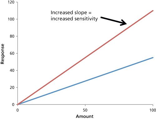
For MS, increased sensitivity is directly related to an absolute increase in the ion count (S = signal) because of more efficient ionization, ion transmission, and ion detection. For chromatography-based MS systems, the net benefits are taller peaks (signal) across the calibration range and improved precision (percent relative standard deviation [%RSD]) that extends the lower end of the calibration range (5). This definition might seem unambiguous, but the observed sensitivity can be influenced by factors beyond increased ion count. Increasingly the voltage on the electron multiplier (EM) will apparently increase the slope, but this is merely amplification of the signal (and the noise), not higher ion count. Whenever sensitivity is evaluated, it must not be compromised by instrument settings like EM gain.
Limit of Detection
For analysis of real samples, a better metric is LOD (3). The LOD can be defined as the smallest amount (or concentration) of analyte that can be detected with an acceptable SNR (typically 3). SNR, and therefore LOD, is a relative measurement. LOD can decrease because the signal has increased, the noise has been reduced, or a combination of increased signal and decreased noise. LOD can decrease even if there are fewer ions (S) produced, transmitted, and detected as long as the noise (N) has decreased by a larger percentage. Under these circumstances LOD decreases (higher calculated SNR) while sensitivity decreases (lower signal). As such, the goal of increased ion count and improved precision may be missed by calculated SNR.
The fundamental difference between sensitivity and limit of detection is illustrated in a comparison of MS and tandem MS (MS-MS) (2,6). MS-MS reduces chemical noise, increasing SNR in the analysis of real samples, and thereby decreasing LODs. Over the last two decades, the statement that “MS-MS is more sensitive than MS” has been made in many presentations and included in many articles. But is this true? In the MS-MS process, the ion count for any product ion (MS-MS mode) is always less than the ion count of the precursor ion (in MS mode). The MS-MS product ion count is lower because of the dissociation of a single precursor ion into multiple product ions and transmission losses through multiple stages of the MS. Thus, the sensitivity of MS-MS is always lower than that of MS.
If the primary benefit of MS-MS is not increased signal (that is, higher sensitivity), why is MS-MS so widely accepted for trace analysis? The primary benefit is reduced chemical noise because of the selectivity of the MS-MS process. A matrix ion that yields an isobaric interference with the analyte precursor ion has a lower probability of also yielding the same MS-MS product ions as the analyte’s product ions; furthermore, the MS-MS product ion is measured against an ultralow noise background that was swept clean of other interfering ions through the isolation step of the first analyzer. MS-MS reduces or eliminates sources of chemical noise and yields baselines that are much flatter and quieter than MS. For many MS-MS applications, the decrease in baseline noise is much greater than the decrease in signal. Even though the peak intensity (S) is less, it is easier to integrate that smaller peak against the quiet, flat baseline. The result is improved (lower) LODs for the MS-MS process despite decreased (lower) sensitivity.
Ensuring a Meaningful Standard for Signal-to-Noise Ratio
Is it possible to ensure a meaningful standard for SNR? This is another important question, and a question that has been addressed by numerous regulatory agencies. The US Environmental Protection Agency (EPA) in Analytical Detection Limit Guidance states, “Samples spiked in the appropriate range for an MDL determination typically has a SNR in the range of 2.5 to 10” (7). The European Medicines Agency (EMA) similarly states, “A SNR between 3 or 2:1 is generally considered acceptable for estimating detection limit” (8).
The EPA guidelines go on to state, “If the signal-to-noise ratio is greater than 10, the spike concentration is usually too high, and the calculated MDL is not necessarily representative of the LOD.” Vendor SNR specifications of 1000, 10,000, and 100,000 clearly violate these guidelines. Rather than decrease the concentration of the test standard to follow EPA guidelines, the amount injected has remained constant and SNRs have increased to extremely high values that would never be accepted by the EMA, EPA, or many other regulatory agencies. In summary, vendor SNR specifications no longer follow acceptable analytical guidelines.
But a recommended guideline such as SNR < 10:1 for the standard or sample to be acceptable is only part of this issue. A meaningful SNR also requires standardization of the method conditions. In the 1980s and early 1990s, every gas chromatography–mass spectrometry (GC–MS) vendor specified the mass range, data rate, and GC peak width at half height (W½) for the SNR specification. Today’s vendor SNR specifications lack these details which, in turn, create ambiguity in the height of the chromatographic peak (S) for a given amount injected on column. A narrow, taller peak from a shorter column or faster temperature ramp appears to improve MS sensitivity even though there is no increase in MS ion count. Valid comparisons are impossible with so many undocumented parameters.
Good guidelines for baseline noise do exist. For example, the European Pharmacopoeia (EP) includes detailed requirements for the width of the baseline noise as compared to the width of the chromatographic peak. Following this guideline, the noise region should be measured across a time window that is 20 times wider than the peak width at half height (W½) (Figure 2). For a peak with a 2-s W½, the noise window should be 40 s (9,10). The US Pharmacopeial Convention (USP) 37 standard defines it as follows:
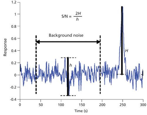
S/N = 2h/hn [1]
where h is the height of the chromatographic peak and hn is the difference between the largest and smallest noise values observed over a distance equal to at least five times the W½ equally spaced before and after the peak (11). The EP and USP guidelines describe reasonable sampling of the baseline, but no vendor follows these guidelines for the SNR specification. In fact, most MS vendors use a noise region as narrow as 5 s and independent of chromatographic peak width. For a 2-s W½, a 5-s noise window would be eight times shorter than the EP guideline and two times shorter than the USP guideline.
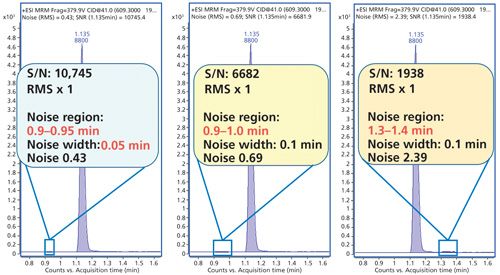
Other regulations provide guidance on the position of the noise measurement. For example, the ACS committee on environmental improvement stated, “peak to peak noise (sdsignal = sdnoise) measured on the baseline close to the actual or expected analyte peak” (12). Vendor specifications do not adhere to these recommendations and have implemented software algorithms that automatically search the entire available baseline to find the lowest possible noise in any part of the baseline-perhaps quite far from the test compound peak. As a result, the reported noise is often not representative of the typical baseline noise, and the SNR is inflated by the autoselected, lowest possible noise (Figure 3).
How Noisy Is the Noise?
Aside from selectivity improvements that reduce chemical noise from the sample matrix, the magnitude of instrument noise has been lowered by numerous changes to the chromatography and MS instrumental components. GC–MS neutral noise generated by metastable helium atoms reaching the vicinity of the detector is an excellent example for significance of these changes. Three decades ago, neutral noise was buried under other noise from column bleed, electronics, and diffusion pump oil. As a result, GC–MS descriptions never mentioned neutral noise. With the advent of ultralow-bleed columns, clean vacuum, and highly selective MS-MS configurations, neutral noise became a highly visible noise component that could no longer be ignored, especially during installation tests of ultraclean, new systems. All vendors responded with designs such as moving the detector off axis from the ion source that reduce this source of noise in electron ionization (EI) systems.
SNR has been increased by the elimination of neutral noise, even though the signal did not increase. Installation specifications appear improved, but what was the real value for routine applications? For GC–MS in selected ion monitoring (SIM) or scan mode, some benefit might be realized for very simple matrices such as air or drinking water, but more complex matrices typically generate enough chemical noise to overwhelm the less intense neutral noise. SNR for complex matrices did not increase. For GC–MS-MS, the benefit is greater since a large component of chemical noise is eliminated by MS-MS, but high volume analysis of food commodities, biological fluids, and complex environmental samples will often generate chemical noise much greater than that measured at installation checkout. SNR for these complex samples may not increase.
The elimination of neutral noise has definitely increased SNR EI installation specifications, but it is even more misleading to compare the installation specification to SNR during routine analysis. With the additional selectivity of MS-MS or high-resolution MS, the noise of a new system draws even closer to zero. Under installation conditions, the SNR can be remarkably high, but that high SNR may never be reproduced on real samples with multiple sources of noise from the matrix, buffers, gases, septa, and aging columns.
A Computer’s View of MS Noise
With the disappearance of strip chart recorders and rulers from the modern MS laboratory, the measurement of signal and noise has been relegated to the PC workstation with the expectation of a better, more consistent determination. Under PC control, the relevance of vendor SNR specification has been further impacted by the mathematical treatment of the noise before visualization in the plot and calculation of SNR.
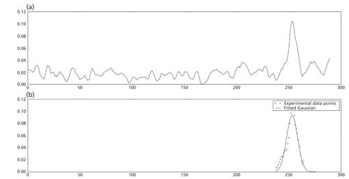
Baseline noise at installation is fundamentally very quiet and stable, but digital filtering by high performance embedded processors is able to massage noise to values approaching zero. As a result, the calculated SNR increases to very high values even though the MS ion count may be low. Digitally smoothed plots look increasingly impressive (Figure 4), but the appearance may disguise poor analytical sensitivity. Replicate injections (%RSD) are required to identify imprecision generated by low ion count and inferior sensitivity.
Is IDL a Better Standard than SNR?
It is probably fair to say that no standard is perfect; however, most scientists would quickly agree that a statistical approach is always preferred. Vendor SNR specifications have typically been based on a single injection that passes a prescribed value, but a single injection is clearly not a good statistical model. Most scientists would also agree that any decision based on a single sample has questionable validity, especially when the imprecision of the method is unknown.
As with SNR parameters, it is probably best to place this decision in the hands of the regulatory agencies. Both the EPA and EMA suggest a statistical alternative to SNR. For the EMA, subsection 6.3 states that the detection limit can be calculated based on standard deviation of response (8). For the US EPA, title 40 Protection of the Environment Part 136, states that a method for calculating MDL is also based upon standard deviation calculated on replicate analyses (13). This guideline has been a fundamental component of US EPA methods for several decades.
In 2010, Agilent Technologies adopted the US EPA’s statistical approach for MDL as the foundation for a new instrument detection limit (IDL) specification (Figures 5a and 5b). The term instrument was substituted for method since the measurement uses a simple standard rather than following a complete method with sample preparation and other steps.
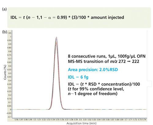
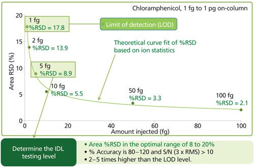
Following statistical guidelines, the amount injected into the chromatographic system is ideally within a factor of 5 of the calculated IDL (Figure 6). Injections of larger amount of test compound must be avoided since this compromises the significance of the precision and the IDL calculation. For good statistics, the number of replicate injections should be at least 7, although 8 to 10 is preferred. The parallel between IDL at installation and MDL for routine laboratory analyses simply makes sense as an appropriate comparison. The comparison of IDL and MDL also eliminates the confusion created when the signal is divided by baseline noise that has been massaged and manipulated to the lowest possible value (14).
Vendor Comments about SNR
In the selection process for the purchase of a MS system, SNR has been given a significant position which, in turn, has placed greater pressure on vendors to publish the highest possible SNR specification. But what have other MS vendors actually said about the validity of SNR measurements?
Sciex has taken a clearly established position for several years. A technical note entitled “Defining Lower Limits of Quantitation” states (15)
The LOD (limit of detection) and the LOQ (limit of quantitation) are often defined as the concentrations which yield a measure peak with S/N of 3 and 10, respectively. However, as will be described, this method can be misleading and should not be used when evaluating instrument performance, and should particularly be avoided when comparing one instrument model to another.
The note goes on to say (15):
A more practical and statistically correct way to define the LOQ is the lowest concentration where the relative uncertainty on a single measurement is reproducible within +/-20%. In this definition of LOQ, S/N and peak height are still important parameters to consider but are not sufficient to fully define it. Determining the LOQ of a method for an analyte, based on a statistical estimate of uncertainty, requires many injections to accurately characterize the systems response to an analyte and to estimate uncertainty.
The words “misleading,” “avoided,” and “statistically” are keywords in this statement. Gary Impey, the Director of Pharma Quant & Drug Metabolism at Sciex, noted that SNR is only a guideline for analysts to understand where their LODs and LOQs might be, and that end users need to clearly determine what the LOQ is and provide statistical data to prove it (16).
Similar statements from other vendors can be gleaned from the internet. Cautions about the validity of SNR specifications and regulatory-based guidelines for SNR measurements are clearly established by the collective response of Agilent, Sciex, Shimadzu, Waters, and others. The validity of the selection process and benefit to the end user will be increased by the replacement of SNR with a statistical standard such as IDL.
Monitoring Declining Response with IDL-Not with SNR
Because SNR is a relative measurement, it may actually disguise declining response because of contamination of the source or problems in the mass analyzer. Ideally, an operator should be confident that MS response is stable and adequate, but SNR may not provide the confirmation that is needed. For both MDL and IDL, precision of response is always inversely proportional to the magnitude of the MS signal and MS ion count. Deterioration in the signal will result in worse precision, and in turn, worse IDL. Although IDL (at installation) and MDL (during routine use) will require more time to analyze multiple injections, they are both better ways to demonstrate that the mass spectrometer is optimally producing ions in the source and optimally transmitting ions through the mass analyzer-eliminating the ambiguity of SNR. Performance problems can be identified sooner and with greater confidence.
Conclusions
The amazing progress of MS technology has produced high performance systems that definitely need new and better metrics for evaluating instrument performance. SNR can still be used to confirm method performance when there is sufficient, representative noise in the baseline. However, in the highly selective, ultralow noise, digitally filtered world of modern mass spectrometry, SNR alone may provide misleading and inadequate information about system performance. SNR pass criteria at installation may be the result of a single, random capture of a very quiet section of baseline followed by sophisticated digital smoothing that is not representative of any other sample injected into the system. To ensure the mass spectrometer is delivering an optimal ion count and sensitivity, a statistical method such as IDL using sample concentrations approaching the detection limit is essential to an accurate evaluation of performance. IDL tests will extend the installation process, but it will also increase confidence in the success of the installation and better represent the typical performance of the mass spectrometer.
References
(1) T. O’Haver, “An Introduction to Signal Processing in Chemical Analysis,” available at: http://terpconnect.umd.edu/~toh/spectrum/IntroToSignalProcessing.pdf.
(2) R.W. Kondrat and R.G. Cooks, Anal. Chem. 50(1), 81A–92A (1978). DOI: 10.1021/ac50023a006.
(3) J.V. Johnson and R.A. Yost, Anal. Chem. 57, 758A–768A (1985).
(4) K.K. Murray, R.K. Boyd, M.N. Eberlin, G.J. Langley, L. Li, and Y. Naito, Pure Appl. Chem. 85(7), 1515–1609 (2013). http://dx.doi.org/10.1351/PAC-REC-06-04-06.
(5) H. Prest and J. Foote, Agilent 5989–7655EN, “The Triple-Axis Detector: Attributes and Operating Advice” (2008).
(6) R.G. Cooks and K.L. Busch, J. Chem. Ed.59(11), 926–932 (1982).
(7) Analytical Detection Limit Guidance, “Laboratory Guide for Determining Method Detection Limits” (U.S. Environmental Protection Agency, Washington, D.C., 1996). Available at: http://dnr.wi.gov/org/es/science/lc/outreach/publications/lod%20guidance%20document.pdf.
(8) European Medicine Agency, Scientific Guideline (2009). Available at: http://www.ema.europa.eu/docs/en_GB/document_library/Scientific_guideline/2009/09/WC500002662.pdf.
(9) General Text 6.0, 2.2.46 “Chromatographic Separation Techniques,” European Pharmacopoeia (European Directorate for the Quality of Medicines, Strasbourg, France, 2008), pp. 75.
(10) R. Boqué and Y. Vander Heyden, LCGC Europe 22(2), 82–85 (2009).
(11) General Chapter <621>“Physical Tests-Chromatography” in United States Pharmacopeia 37 (United States Pharmacopeial Convention, Rockville, Maryland), pp. 6. Available at:
.
(12) D. MacDougall and W.B. Crummett, Anal. Chem.52(14), 2242–2249 (1980).
(13) Title 40: Protection of Environment; Part 136 - Guidelines Establishing Test Procedures for the Analysis of Pollutants; Appendix B to Part 136 - Definition and Procedure for the Determination of the Method Detection Limit - Revision 1.11. (U.S. Environmental Protection Agency, Washington, D.C.).
(14) Agilent 5991–6298EN, “Instrument Detection Limit: A Superior Standard of Performance for GC/MS and LC/MS” (2015).
(15) AB SCIEX 0923810-01, “Defining Lower Limits of Quantitation: A Discussion of Signal/Noise, Reproducibility and Detector Technology in Quantitative LC/MS/MS Experiments” (2010).
(16) Author personal communication with G. Impey.
Terry L. Sheehan is the Director of MS Business Development at Agilent Technologies, Inc., in Santa Clara, California. Richard A. Yost is the Colonel Allen and Margaret Crow Professor and Head of the Department of Analytical Chemistry at the University of Florida in Gainesville, Florida. Direct correspondence to: terry_sheehan@agilent.com
New Study Reviews Chromatography Methods for Flavonoid Analysis
April 21st 2025Flavonoids are widely used metabolites that carry out various functions in different industries, such as food and cosmetics. Detecting, separating, and quantifying them in fruit species can be a complicated process.
University of Rouen-Normandy Scientists Explore Eco-Friendly Sampling Approach for GC-HRMS
April 17th 2025Root exudates—substances secreted by living plant roots—are challenging to sample, as they are typically extracted using artificial devices and can vary widely in both quantity and composition across plant species.
Common Challenges in Nitrosamine Analysis: An LCGC International Peer Exchange
April 15th 2025A recent roundtable discussion featuring Aloka Srinivasan of Raaha, Mayank Bhanti of the United States Pharmacopeia (USP), and Amber Burch of Purisys discussed the challenges surrounding nitrosamine analysis in pharmaceuticals.


