What Is “Dead” Volume and Why Should Chromatographers Worry About It?
LCGC Europe
The term dead volume often comes up in chromatography discussions and literature. This month we address the nature of this phenomenon, when it can become a problem that affects chromatographic results, and how to understand and take control of it.
John V. Hinshaw
, GC Connections Editor.
The term dead volume often comes up in chromatography discussions and literature. This month we address the nature of this phenomenon, when it can become a problem that affects chromatographic results, and how to understand and take control of it.
Chromatographers embrace some unique terminologies that can be confusing for the uninitiated. Split–splitless injection, temperature programming, and peak capacity are some examples of terms that are easy to misconstrue. Even the word column is ambiguous or misleading - especially when translated into various languages - without qualifying with the prefix chromatography. In the chromatographer’s argot, dead volume arguably stands out as one of the most poorly understood terms. Was this volume alive at some point? What happened to cause its demise? Does it behave differently on All Saint’s Eve or Halloween? Joking aside, the effects of dead volume are seen in nearly every chromatogram and more so in gas chromatography (GC) than in liquid chromatography (LC). If dead volume effects are small they are hard to distinguish from other phenomena with similar effects, such as solute adsorption. A large amount of dead volume, however, will affect chromatography separations to their detriment and will compromise peak separation and quantification.
Dead Volume
In the sense used here, dead signifies unmoving, stagnant, or unswept, and volume means a space other than a column through (or by) which the chromatography mobile phase flows while solutes are present. A gas volume doesn’t have to be completely unswept or devoid of flow; it can still seriously affect the chromatography as we will see. In fact, it is rare to see a completely dead volume that experiences no mobile phase flow at all. Inlets, detectors, and gas fittings can all suffer from the effects, and manufacturers go to great pains to minimize dead volume in their instruments. The dead volume of a chromatography system is defined by the International Union of Pure and Applied Chemistry (IUPAC) (1) as an obsolete term equal to the mobile phase volume that solutes experience outside of the column, equivalent to the extracolumn volume. Unfortunately, there is a good deal of confusion about this definition because the term dead time in chromatography usually signifies the unretained peak time in GC, or the time for one column’s worth of mobile phase in LC, to pass through the column. In this sense, dead refers back to a bygone age when the pen of a chart recorder sat immobile between injection and the elution of the earliest possible peak. The dead time is preferentially called the holdup time.

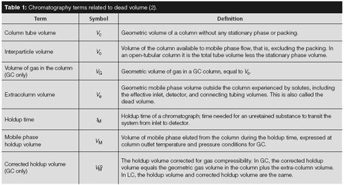
By converting time to volume, a different meaning of dead volume is inferred from the dead or holdup time. It’s not found so much in the GC world, but liquid chromatographers have been known to refer to the volume of mobile phase in a column as the dead volume. As an attempt to clarify, Table 1 lists some volume and time terms related to this concept. The extracolumn (dead) volume may be calculated by measuring the holdup volume and subtracting it from the geometric column mobile-phase volume. The dead volume is quite small in well-designed chromatography systems and in practice it is neglected when performing calculations related to the terms in Table 1. However, it is instructive to examine the effects of excess dead volume on injection and detection.

Figure 1:
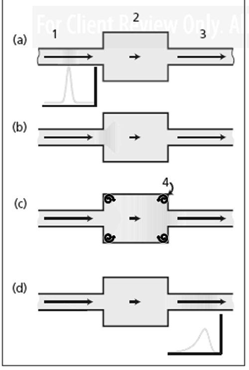
Dead volume effect: (a) Solute band approaching dead volume, (b) solute band entering dead volume, (c) flow and diffusion distributes solutes into dead volume, and (d) broadened, tailing, and delayed solute band leaves dead volume. 1 = inlet tube, 2 = dead volume, 3 = outlet tube, 4 = unswept flow eddies. But before we address truly dead volume, what happens when there is an excess of volume that is not well swept by flowing gas? Figure 1 illustrates that concept in general. Here, an extra volume is connected in the midst of a tube. Mobile phase - the carrier gas in GC - flows through the tube from the left and through the extra volume. The mobile phase then exits on the right-hand side. The tube represents a chromatography column and the volume could represent an excess area inside a detector, for example. In Figure 1(a), carrier gas flows at a steady linear velocity as a solute band approaches. Its profile is presented as a Gaussian peak. In Figure 1(b), the solute band has entered the excess volume from the left and has begun to spread out inside it. Remember that in chromatographic processes, solutes constantly diffuse through the mobile phase in all directions while being pushed along simultaneously by its flow. As the solute band starts to flow into the excess volume, the solute molecules will diffuse away from the band in all directions. They are free to diffuse throughout the volume, and depending on the flow, volume, and diffusivity they will fill it to some degree. In GC, solute diffusion rates are rather large, on the order of 0.2–0.6 cm2/s for C6–C10 hydrocarbons. Thus, GC separations are more prone to diffusive effects while LC separations, where solute diffusion rates are much smaller, tend to experience problems with ineffectively swept dead volumes. Under the influence of continuing carrier flow as well as diffusion, solute molecules will eventually reach the exit of the extra volume and continue into the exit tube section, as diagrammed in Figure 1(c). Finally, the bulk of the solute band will be swept out (see Figure 1[d]). The net effect of this arrangement is to broaden and create some tailing in the peak profile, as well as delay the transit of the solute band. The excess volume section in Figure 1 has a diameter about three times that of the incoming and outgoing tubes, so its volume per unit length is nine times greater and the gas linear velocity through the excess volume is one-ninth that in the tubes. Hopefully this extreme situation will not occur in a real separation! Thus, a time delay is imposed on the solute band, compared to that in the absence of the excess volume. The arrows in Figure 1 give an idea of the relative linear velocities or flows in the various areas shown. As the solute band fills the excess volume it is diluted by additional mobile phase that flows in. An exponentially modified Gaussian (EMG) peak shape is a good approximation for the net effect of the excess volume. This is the profile shown in Figure 1(d), but the reality is more complex. For example, the flow pattern throughout the extra volume is nonuniform, and eddy pockets may exist at the corners as shown. This will further spread and tail the solute band as solute molecules that may be trapped will need to diffuse out of those areas.
GC Detectors
Figure 1 is a basic illustration of why makeup gas is needed in many GC detectors. Designed for older packed column technology, when open-tubular (capillary) columns are connected with no further modifications to the detector the situation is very close to what is shown here. The active detector components such as a flame jet or 63Ni foil would sit just beyond the exit tube on the right-hand side.

Figure 2:
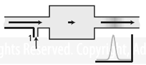
Dead volume in a detector. Here the addition of makeup gas at 1 causes the solutes to be swept from the dead volume rapidly, thereby reducing peak tailing, broadening, and delay. Figure 2 adds a makeup gas inlet to illustrate where makeup gas would be added to a detector. If the makeup gas flow were greater than nine times the carrier gas flow, the excess volume would contribute only a small amount to peak tailing and broadening. Depending on the shape of the excess volume, however, the result might not be perfect. Solute molecules could still become trapped in poorly swept corners or other obstructed areas. Therefore, many detectors have the capability of placing the column tip as close as possible to the active area, limiting how much exposure occurs to areas of excess volume. The need for makeup gas in detectors goes beyond just sweeping out excess volume. A flame ionization detector needs specific flows of carrier gas, hydrogen, and air through and around the flame jet. Capillary column carrier gas flows are usually too low to satisfy this requirement, so adding carrier makeup gas also brings the total carrier flow through the flame jet up to an optimum level. An electron-capture detector functions in the presence of nitrogen or a mixture of methane in argon. If the carrier gas is not nitrogen then it can be added as makeup gas to sweep excess volume in the electron-capture detector as well as provide the needed chemical functionality. Of course, some detectors such as a thermal conductivity detector may experience a loss of sensitivity because of dilution with the added makeup gas.
GC Inlets

Figure 3:
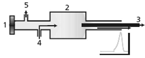
Dead volume in a split–splitless inlet. 1 = septum nut and injection point, 2 = split inlet liner volume, 3 = capillary column with entrance inside split liner, 4 = carrier gas entrance, 5 = septum purge exit. Unswept dead volume also influences injection. Solute and solvent may enter into the area near the inlet septum by diffusion or under the influence of the internal pressure pulse caused by solvent vaporization. Septum purge flow, shown in Figure 3, helps to sweep these away from the main carrier flow and prevent the tailing solute profile that could result as these molecules otherwise would be free to diffuse back into the carrier stream. A split–splitless injector resembles the arrangement of Figure 3. In this case, the sample band is introduced and vaporized directly in a larger volume area - the split inlet liner. For split injection the carrier flow is high enough to rapidly sweep a fraction of the sample from the liner into the column. The story is a bit different in splitless injection or, as I like to call it, “split-later injection”. The total carrier gas flow through the inlet liner is purposely kept at the column flow rate while the sample is introduced and vaporized. Sample vapour is then swept into the column entrance for a minute or so, which usually means that from 80% to 95% of the sample vapour enters the column. The situation is much like Figure 1 at first, so sample takes on a broad and tailing profile inside the column. Next, however, the carrier-gas flow through the inlet is increased up to split flow levels, by a factor of ten to several hundred times. This high flow rapidly sweeps out the remaining sample from the inlet and cuts off the transfer of sample into the column, as illustrated by the peak profile as it exits the inlet in Figure 3. The problem of the broad and tailing injection profile in the column itself is remedied by arranging the stationary phase and temperature to narrow and refocus the sample in a combination of thermal and solubility trapping.
Conclusion
Dead volume effects can cause serious trouble for chromatographers. Excess dead volume can make peaks tail and broaden and thereby compromise peak resolution that otherwise would be available from a column. Modern chromatographs are not as subject to dead volume problems, but as plate numbers are driven to new limits by high-performance, high-speed GC and ultrahigh-pressure liquid chromatography (UHPLC) separations, increasing care must be exercised to keep the dead volumes down. Even with conventional GC systems, it’s not so difficult to position a ferrule the wrong way or insert a capillary column the wrong distance into the inlet or detector. Sometimes dead volume issues only become apparent when upgrading a method to new levels or when changing from a helium to hydrogen carrier to gain some separation speed. With a little bit of foreknowledge, these difficulties can be caught and fixed before too much time is wasted.
References
L.S. Ettre,
Pure and Applied Chemistry
,
65
(4), 819–872 (1993). L.S. Ettre and J.V. Hinshaw,
Basic Relationships of Gas Chromatography
(Advanstar, Cleveland, Ohio, USA, 1993). “GC Connections” editor
John V. Hinshaw
is a Senior Scientist at Serveron Corporation in Beaverton, Oregon, USA, and a member of LCGC Europe’s editorial advisory board. Direct correspondence about this column should be addressed to “GC Connections”, LCGC Europe, Hinderton Point, Lloyd Drive, Ellesmere Port, Cheshire, CH65 9HQ, UK, or email the editor-in-chief, Alasdair Matheson, at amatheson@advanstar.com

Polysorbate Quantification and Degradation Analysis via LC and Charged Aerosol Detection
April 9th 2025Scientists from ThermoFisher Scientific published a review article in the Journal of Chromatography A that provided an overview of HPLC analysis using charged aerosol detection can help with polysorbate quantification.
Analyzing Vitamin K1 Levels in Vegetables Eaten by Warfarin Patients Using HPLC UV–vis
April 9th 2025Research conducted by the Universitas Padjadjaran (Sumedang, Indonesia) focused on the measurement of vitamin K1 in various vegetables (specifically lettuce, cabbage, napa cabbage, and spinach) that were ingested by patients using warfarin. High performance liquid chromatography (HPLC) equipped with an ultraviolet detector set at 245 nm was used as the analytical technique.
Removing Double-Stranded RNA Impurities Using Chromatography
April 8th 2025Researchers from Agency for Science, Technology and Research in Singapore recently published a review article exploring how chromatography can be used to remove double-stranded RNA impurities during mRNA therapeutics production.


