The LCGC Blog: Hydrogen Carrier Gas for Gas Chromatography Mass Spectrometry (GC–MS) – a Practical Guide
There has been much written on this subject in recent years, driven primarily by the somewhat erratic supply chain for helium and its volatile pricing. I’m not a believer in overhyping the (numerous) “helium crises,” and my recent blog on the state of the global helium supply chin issues, the discovery of new reserves, and the development of extraction technologies hopefully went some way to explaining that we won’t be running out of helium for laboratory use any time soon (1). This being said, it is a fact that most of us will be experiencing rising helium costs and in some cases, caps on supply, or an inability to initiate new supply contracts from providers.
The many articles and guides on the use of hydrogen carrier gas with GC–MS systems, primarily from manufacturers, do a good job at explaining the aspects one needs to consider, and I also wrote a relatively recent blog on the subject that can be found here (2). Despite the proliferation of these guides, I’m frequently asked about the “real-life” viability of making the switch to hydrogen for gas chromatography with mass spectrometric detection and any pointers or checklists that may be available to ensure that ”all bases are covered” when preparing for the switch. Based on my own experiences, and those of colleagues and contacts, I’ve prepared what I hope is a succinct and focused guide on the factors one needs to evaluate to properly inform the decision to switch, and what to expect on the implementation journey.
Hydrogen Supply
Can be achieved via the use cylinders or generators. Ensure you get the right generator to satisfy the required pressure/flow for the number of GC instruments and don’t forget to consider the requirements for the high flows associated with split injection techniques. Manufacturers of hydrogen generators will assist with selecting the right generator to satisfy the capacity (pressure and flow) requirements for your setup. There are two primary technologies used by generator manufacturers (electrolysis of water using metallic electrodes, or ionomeric proton exchange membranes), and both can produce hydrogen at the required pressure/flow and purity for GC–MS. It is worthwhile checking the ongoing end-user and vendor maintenance requirements when selecting the generator. If you decide to go with cylinder supply, then bear in mind that hydrogen regulators are different from those used for other gases and are typically stainless steel and left-hand thread. See also comments on the next section on hydrogen safety.
Hydrogen Safety
Hydrogen is combustible at concentrations between 4 and 75% in air and leaks in confined spaces (such as the GC oven, where it is more likely that the hydrogen concentration will exceed 4%) can cause explosions. Hydrogen burns with an almost invisible flame, and therefore may present a considerable safety risk.
Hydrogen that escapes rapidly from high pressure (as in a runaway leak from a cylinder or regulator) can self-ignite, and “snubber” devices are available from a number of manufacturers to mitigate the risk of a runaway escape from the cylinder.
Manufacturers have incorporated several safety features into more modern instruments that include low pressure safety shutdown (if pressure setpoints are not met or maintained due to leaks), flow limiting frits within on-board gas regulators and pressure control devices, explosion limiting oven designs and on-board hydrogen leak sensing and shut down. Note that this last feature may be an optional extra, depending upon your vendor.
Split and septum purge vent flows and roughing (foreline) pump exhausts should be connected to a negative flow laboratory vent system in order to avoid hydrogen accumulation in the laboratory, however it’s worth speaking with your safety team to risk assess the possibility of actually achieving 4% hydrogen concentration in the laboratory. This is especially true when using hydrogen generators – where hydrogen is produced “on-demand” and very little gas is stored “on board” the generator (typically 50 mL or so), and safety features such as low-pressure cut-off and flow limitation devices significantly reduce the risk of reaching the critical 4% concentration in the general laboratory environment. A small laboratory with several GC–MS systems using hydrogen carriers will clearly present a higher risk than a larger laboratory with only one or two GC–MS systems.
Ensure that you consult fully with your laboratory safety team prior to making the decision to switch to hydrogen carrier. In my experience local rules, regulations, and requirements differ widely, and sometimes require more extensive preparation of laboratory infrastructure, which can be both costly and time consuming. Consider using hydrogen cylinders during initial method evaluation and venting outside of the laboratory, prior to making more costly investments into gas generators or laboratory negative-pressure infrastructure.
Carrier Flow-Rate Considerations
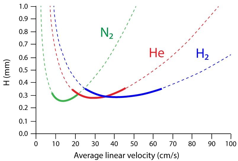
Hydrogen is significantly less viscous than helium (0.089 versus 0.176 kg/m3), resulting in significantly lower head pressures when matching column flow rates with methods using helium carrier. Remember also the van Deemter curve of efficiency (plate height) versus carrier gas linear velocity (Figure 1), shows that hydrogen is most efficient (such as results in the narrowest chromatographic peaks) as a carrier gas at higher linear velocities‑ typically in the range 30–60 cm per s. Helium, on the other hand, demonstrates highest chromatographic efficiency at linear velocities of around 20– 40 cm per s. It is also worthwhile bearing in mind that the efficiency of hydrogen very quickly reduces, and therefore so may chromatographic resolution for closely eluting peaks, at linear velocities below 35 cm per s, but this is not the case when pushing the linear velocity greater than 55 cm per s, therefore it’s more prudent to work a slightly higher carrier linear velocity than you may think necessary.
Figure 1: Influence of carrier gas and linear velocity on theoretical plate height. The solid lines indicate the regions in which the plate height (H) is within 25% of the minimum plate height value (Hmin) which is often known as the Optimum Practical Gas Velocity (OGPV). Theoretical data for a 50 m x 0.25 mm column at 100 oC for an analyte of k’ = 10.0.

All of the above means that hydrogen is better used with lower internal diameter GC columns (0.25mm and below), because these columns tend to generate higher linear velocities and take advantage of hydrogen’s higher inherent efficiency.
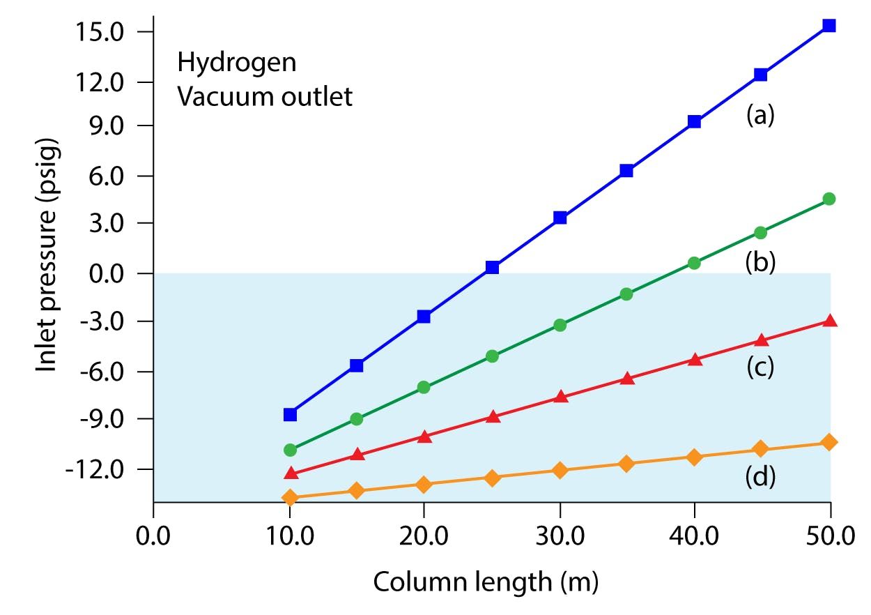
If one tries a simple “switch” from helium to hydrogen carrier, using exactly the same method conditions, you may well find that the required GC inlet head pressure is very low, or even negative, given that the column has a vacuum-based detector at its outlet. The use of electronic pressure or pneumatic controllers below around 5 psi is not recommended by most manufacturers, due to the difficulties in reproducibly controlling the gas flow as these low pressures. Negative inlet pressures should be avoided at all costs as they can lead to instrument low-pressure shutdowns and damage to the column and inlet components due to air ingress. For example, the very popular column dimension of 30 m x 025 mm x 0.25 mm cannot be readily used with hydrogen carrier in GC–MS applications under typical operating conditions. With an initial oven temperature of 40 oC and an outlet flow rate of 1 mL/min, the required hydrogen head pressure would be -0.037 psi with a linear velocity of 53 cm per s. Figure 2 demonstrates that 0.32- and 0.53-mm internal diameter columns are practically unusable with GC–MS.
Figure 2: Plots of inlet pressure vs. column length, with hydrogen carrier gas and vacuum compensation on. Column inner diameters (mm): (a) 0.20, (b) 0.25, (c) 0.32, (d) 0.53; column temperature: 50 °C; average linear velocity: 40 cm per s. The blue shaded area designates negative inlet pressures.

One may be tempted to increase the carrier gas flow rate, given that hydrogen retains its high chromatographic efficiency at higher linear velocities, and at 1.5 mL/min outlet flow the inlet pressure is 3.26 psi (65 cm per s) and at 2 mL/min the required pressure is 6.04 psi (76 cm per s). This all looks relatively promising until we consider the pumping capacity of MS detector systems when using a much lower viscosity carrier gas. Most manufacturers will limit the column flow rate to 2.0mL/min, however what they may not reveal is that the source and detector efficiency will decrease markedly as pressures increase above (approx.) 0.05 m Torr, and this effectively means that most systems are limited to the 1.0 to 1.5mL/min column flow rate range (depending on your sensitivity requirements).
One also needs to bear in mind these maximum flow requirements if using pressure pulsed injection, as exceeding the pumping capacity of the detector by any significant amount could result in pooling of the carrier inside the ion source, where the risk of explosion increases significantly. A hydrogen pressure pulse at 40 psi would lead to a flow rate into the detector of 14 mL/min. MS systems with turbomolecular pumps, as opposed to diffusion pumps, can tolerate flow rates (but should not be used for analysis) up to around 3.0–3.5 mL/min, before pooling of the carrier will occur. It’s very important to know the limits of the pumping system when switching from helium to hydrogen, and not to exceed these under any circumstances.
Method Translation
Folks I know who are on the hydrogen switch journey, tend to fall into two camps: those who wish to simply get the same results as they did before with their helium carrier, and those who wish to exploit the separation speed advantages offered by hydrogen’s efficiency at higher linear velocity. If you fall into either of these camps, I would highly recommend one of the method translator tools available from instrument vendors, for all of the reasons mentioned above and for the excellent practical insights that one can glean from undertaking the translation exercise, prior to any hands-on method redevelopment.
In almost all cases, a simple swap of hydrogen for helium is either not possible or just doesn’t work as well as the end user hoped‑that is, despite efforts at “tweaking” the method, chromatographic results obtained don’t closely match those obtained using helium carrier. Primarily, we should be carefully noting the preservation of peak retention time order (which should be confirmed with MS identification of individual analytes), and any loss of resolution between target analytes.
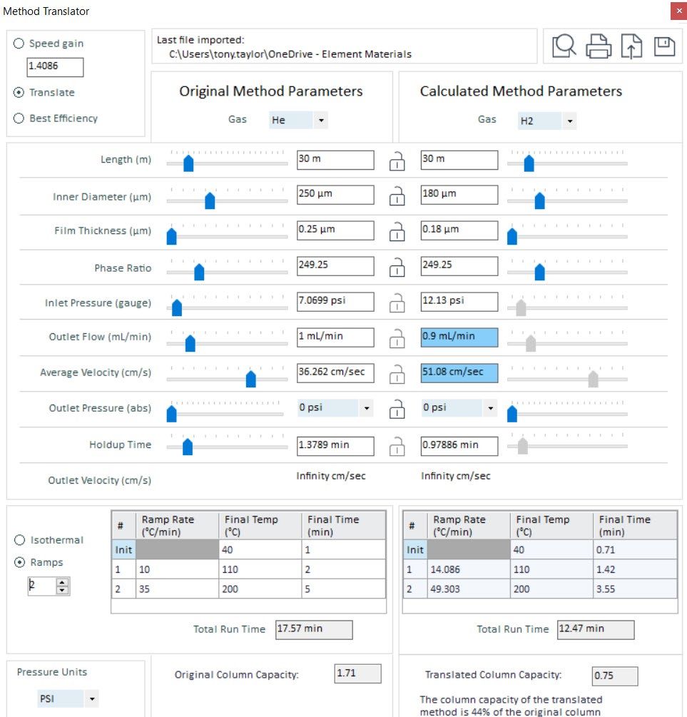
In my experience, most chromatographic “issues” encountered when attempting a method translation can be overcome using a different column dimension. I’ve tried to highlight this in Figure 3 below.
Figure 3: Method translation from helium to hydrogen carrier, attempting to emulate the original chromatography in so far as possible. Areas highlighted in red are further discussed in the text below. (Method translation tool from Agilent Technologies, Santa Clara, USA)

By using a column of equivalent length, but with a 0.18 mm internal diameter, the column head pressure required is approximately 12 psi, which will be reproducibly achieved and maintained using the GC instrument pressure control system. The flow rate into the MS instrument is 0.9mL/min, which is an optimal value, and the linear velocity is within the optimum efficiency range for the hydrogen carrier gas. It should be noted also that the translation tool optimizes the oven temperature program to maintain optimum efficiency for the separation. All this being said, it should be noted that the analysis time has reduced from 17.57 min to 12.47min, which will almost certainly require a change to the start and stop times for any selected ion monitoring groups used for quantitative analysis. It should be further noted that, even though the phase ratio is maintained (this is very important to retain the separation selectivity), the column capacity is 0.75 compared to 1.71 in the original method. This is primarily due to reduction in film thickness of the stationary phase and may require a reduction in the analyte loading on the new column. This can be achieved by reducing the injection volume or the analyte concentration, according to the ratio of capacity reduction (meaning loading should be reduced to 44% of the original column loading—such as 0.75/1.71).
Requirements for MS Hardware
For long term hydrogen use with a GC–MS system, it is recommended that all copper tubing be replaced with stainless steel. I’ve never really managed to get a fully satisfactory response as to why, however, it may be a risk reduction measure because copper will eventually become brittle over time and may be more susceptible to cracking, and then for leaks to develop.
Different manufacturers have different requirements for changing source components, and one should follow their advice if any ion source components need to be changed. The requirement for changes to source components is typically driven by a reduction in source/ion beam contact which can lead to increased peak tailing and potential hydrogen hydrogenation reactions or is driven by a need to increase the pumping efficiency within the ion source region, due to the reduced viscosity of hydrogen.
Initial Conditioning
In my experience, conditioning of the instrument can be tricky, and one needs to have perseverance. Active hydrogen species are highly efficient at “cleaning” metal surfaces throughout the system, and this will end up in the detector during the conditioning phase.
The instrument should be initially conditioned at atmospheric temperature, but with the carrier gas flowing, for more than one h prior to turning on the heated zones in the GC and MS instruments. The system should then be brought to temperature and allowed to condition for a reasonable time, prior to the MS being tuned. This “reasonable time” will vary from manufacturer to manufacturer however, in my experience, this can range from overnight to more than one week!
During initial MS instrument tuning and sample injections, one needs to be prepared for a shock! You may observe signals for all ions up to around 300–500 m/z, a higher background (and therefore a reduced sensitivity) and severe tailing for many analyte peaks. While this sounds like a list that should put any prospective user of hydrogen carrier in GC–MS off for life, it really is a transient phase, at least for most systems and analytes.
The key to effective source conditioning is to apply increased temperature and to keep the filament(s) on for an extended period (and this is typically overnight). One can keep the filaments on by injecting very small volumes of solvent, or by carrying out an injection of a very small amount of air (the minimum injection volume possible with your system) and have a very long method run time. During this time, the applied detector voltages should be reduced to lower values to avoid burning out the detector with the very high signals which will be generated by the high ion currents during the conditioning phase.
While the conditioning of the ion source may result in lower background and reduced peak tailing, one needs to accept that for certain applications, it may be that lower sensitivity and peaks with increased asymmetry may be unavoidable. While it would be very helpful to list types of analytes or applications that may suffer these issues, unfortunately, I’ve yet to come across a set of solid rules that can be used to predict problems of this type, however a useful average reduction in response (peak area) using hydrogen carrier is on the order of 1.5 times lower.
Hydrogen Reactivity
As is noted above, unlike helium, hydrogen is not an inert gas, and as such one needs to expect some level of reactivity with susceptible analytes. This may mean a reduction in the quality of library matches with commercially available libraries in which the spectra have been acquired using helium carrier gas. Long term users of hydrogen carrier should consider building libraries of analytes obtained using hydrogen, to improve match quality over commercially available library spectra.
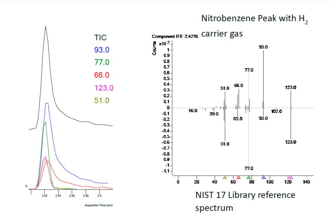
One major instrument vendor analyzed a suite of 20 test compounds with widely varying physio-chemical properties and obtained an average commercially available library match score of 95.8 using helium carrier and 93.0 when hydrogen was used as carrier. While this seems reasonably insignificant, it should be noted that analytes susceptible to hydrogen hydrogenation can suffer large reductions in library match factors, and in this exercise the match for the nitrobenzene analyte reduced from 97.4 with helium carrier to 63.3 using hydrogen carrier.
It is important to understand the potential impact of changes to spectral response and Figure 4 shows changes to the nitrobenzene spectrum and selected ion response using hydrogen carrier versus the NIST 17 library. Of note are the changes in the response due to the ions at 93 and 66 m/z and the respective tailing of these ions within the selected ion plots, indicating the possible hydrogen hydrogenation of the analyte within the system. One should be mindful of the use of these target signals in quantitative analysis, both for the quantitative determination and the use of ion ratios as qualifiers of the analyte identity. One needs to carefully consider the ions selected for quantitation of target analytes when switching from helium to hydrogen and ensure the fidelity of the response or to select alternative ions where possible.
Figure 4: Nitrobenzene spectral and selection ion signal changes when using hydrogen carrier for nitrobenzene. (Courtesy of Agilent Technologies, Santa Clara, USA)

The best way to reduce analyte and active hydrogen species reactions is to reduce residence times within high temperature zones of the instrument and to reduce analyte contact with hot metal surfaces. There are several ways in which this can be achieved, including:
- Keeping residence times in the GC inlet as short as possible, including the use of pressure pulsed injection with splitless injection mode. Take care not to exceed the pumping capacity of the MS system during the pulsed phase of the injection.
- Using liners with restrictions or tapers to avoid analyte contact with the inlet metal surfaces
- Using deactivated metal components wherever possible (use silicon coated or specially deactivated inlet and source components if these are available from your manufacturer)
- Mounting columns slightly higher within the inlet to avoid analyte contact with lower inlet metal surfaces, although check that this does not impact quantitative method performance
- Using manufacturer-recommended MS ion source components
- Using the lowest inlet temperatures possible, or considering the use of cold split or cold splitless injection
- Using high quality or deactivated inlet consumables
Finally, some practical miscellaneous observations:
- It is best to avoid chlorinated solvents (especially methylene chloride) because there is a risk of gaseous hydrogen chloride formation which will erode instrument components. This risk of component erosion will increase with any water present within the sample solvent.
- Ensure that you have a stock of spare MS filaments on hand because lifetimes may be shorter when using hydrogen carrier
- Expect less source cleaning as part of your maintenance routine, as hydrogen is highly effective at “scrubbing” residual sample deposits from EI source components
- Ensure that you have a good quality hydrogen leak detector to check fittings for small leaks on an ongoing basis. If your manufacturer offers you the opportunity to install an on-board hydrogen alarm system, or your employer mandates the use of a laboratory hydrogen alarm system, these can help greatly to improve your personal confidence in the safe use of hydrogen within the laboratory.
I hope that the practical considerations outlined above help to inform your decision to switch to hydrogen and your method translation journey. My principle is to stick with helium wherever possible, however, if your intention is to make the transition due to cost pressures or lack of availability, then with care and attention, the switch to hydrogen carrier for GC–MS applications is both possible and can offer longer term cost savings.
References
(1) https://www.chromatographyonline.com/view/-not-another-helium-crisis-
Tony Taylor

Tony Taylor is the Chief Scientific Officer of Arch Sciences Group and the Technical Director of CHROMacademy. His background is in pharmaceutical R&D and polymer chemistry, but he has spent the past 20 years in training and consulting, working with Crawford Scientific Group clients to ensure they attain the very best analytical science possible. He has trained and consulted with thousands of analytical chemists globally and is passionate about professional development in separation science, developing CHROMacademy to provide high-quality online education to analytical chemists. His current research interests include HPLC column selectivity codification, advanced automated sample preparation, and LC–MS and GC–MS for materials characterization, especially in the field of extractables and leachables analysis.
New Study Reviews Chromatography Methods for Flavonoid Analysis
April 21st 2025Flavonoids are widely used metabolites that carry out various functions in different industries, such as food and cosmetics. Detecting, separating, and quantifying them in fruit species can be a complicated process.

.png&w=3840&q=75)

.png&w=3840&q=75)


.png&w=3840&q=75)


.png&w=3840&q=75)


