The LCGC Blog: How Well Do You Pipette?
At the heart of most chromatographic analyses are the gravimetric and volumetric operations used to prepare samples, standards, and HPLC mobile phases.
Most of us believe we are proficient in these basic laboratory skills but from time to time I like to revisit the skills, theory, and regulatory recommendations for even for most basic operations such as weighing and using pipettes.
I often find that the Standard Operating Procedures we follow tend to be very general and, for the reasons of operational simplicity, do not include the nuance of best practice. These nuances and the latest thinking in good practice are often handled via training courses, which is fine, so long as the training is regularly updated and redelivered to keep us all current.
So, this time I’m going to take a little deeper dive into the requirements for the use of so called “automatic” pipettes.
I’m using myself as a yard stick as we move through the recommendations and good practice, and I’ll be honest and point out (using Note:) those factors I was not aware of or areas where my practice could not always be described as “good!”
I’ve used the following references sources throughout this treatment;
[1] Piston-operated volumetric apparatus — Part 2: Piston pipettes, ISO 8655-2:2002(E)
[2] Piston-operated volumetric apparatus — Part 6: Gravimetric methods for the determination of measurement error, ISO 8655-6:2002
[3] GUIDE TO PIPETTING, Third Edition (2019), Gilson
[4] High Precision Micropipette, Operating Manual, Microlit RBO
[5] Measurement Good Practice Guide No. 69 The Calibration and Use of Piston Pipettes, July 2004 National Physical Laboratory, Teddington, Middlesex, United Kingdom, TW11 0LW
I would say that I make no claim on the correctness of what is written below—it is not advice, simply a personal interpretation on the current guidance and good practice documentation. I’d love to hear from the community if you believe anything in the text is incorrect—I’m always happy to publish corrections and keep my learning journey going!
So, let’s start with choosing the correct pipette for the job and compare and contrast the differences.
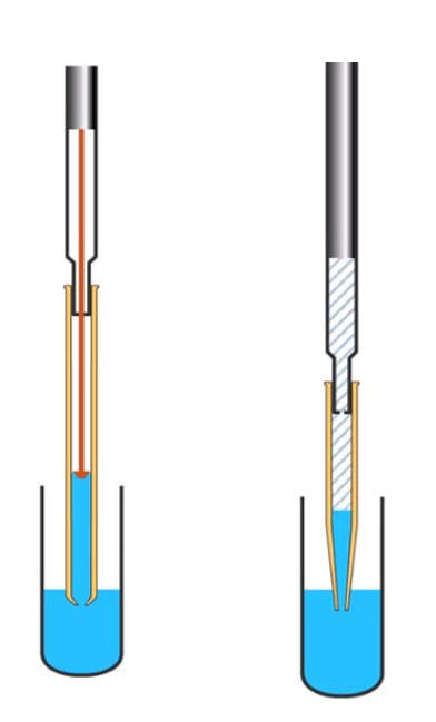
In short, an air displacement pipette has a layer of air between the head of the piston and the liquid within the pipette tip. Air pressure is used to force liquid from the tip. Positive displacement pipettes have an integral piston within the disposable tip and the piston is in contact with the liquid being dispensed. Both types are shown schematically in Figure 1.
Figure 1: Schematic diagram of an air displacement pipette (left) and a positive displacement pipette (right) (image reproduced with permission of CHROMacademy, www.chromacademy.com)
The manufacturers recommendations align well when considering which type of pipette to use for which sample type:
- Use air displacement pipettes for:
- Aqueous solutions
- Biological samples
- Use positive displacement pipettes for:
- Viscous
- Dense
- High surface tension
- Corrosive acids or bases
- Volatile organic liquids
I wondered if, like me, you had been using an air displacement pipette for relatively volatile organic solvents or viscous solutions for years.
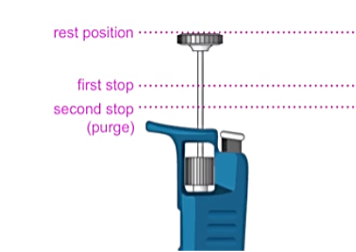
One pipette tip installation for air displacement pipettes: Rather than pressing the pipette shaft firmly and directly down onto the tip (apparently known as “hammering”), it is recommended that a slight twisting motion is used to create a good seal. Tips in racks are convenient (if more costly) for good practice in pipette tip fitting. For positive displacement pipettes, the above guidance should be followed, but once the tip is installed onto the shaft, the tip should be lifted out of the rack and the piston lowered until a “click” is heard as the piston locks into the pipette body. The plunger should then be pressed to the first stop position. Figure 2 contains an explanation of the various plunger positions of a typical piston pipette.
Figure 2: Schematic diagram of the various stop positions of a typical manual piston pipette (image reproduced with permission of CHROMacademy, www.chromacademy.com)
Air Displacement Pipette – Forward Pipetting mode
a) Set correct volume (variable volume pipettes)
When using a variable volume pipette, some manufacturers recommend the volume is dialed using a clockwise motion as the dispensed volume is controlled by a piston spring. For maximum accuracy, the spring should always be set under tension by turning the thumbscrew clockwise.
Operationally, when reducing the volume, slowly move the volume setting dial to the required volume, but when increasing the volume, overshoot the required setting by 1/3 of a turn and then reduce the volume to the desired setting. In this way, the desired volume is always reached using a clockwise motion. Always hold the volume setting at eye level to avoid parallax error.
b) Aspirate an aliquot of the liquid to be dispensed, allow to equilibrate, and dispense to waste
Holding the pipette vertically, smoothly depress the plunger to the first stop position, immerse the tip of the pipette into the liquid to be aspirated to the depth recommended in Table I, and aspirate the liquid by smoothly and steadily raising the plunger to the rest position.

Notes:
If the tip is immersed too deeply, the increased hydrostatic pressure may cause too much liquid to be aspirated or liquid droplets to adhere to the outside of the pipette tip which may be transferred to the receiving vessel. If the tip is not immersed deeply enough, then vortexing may occur, or the liquid level may fall below the tip before reaching the top of the filling stroke. In both cases, too little liquid will be aspirated.
Wait two seconds for the aspirated liquid to move up into the tip and to equilibrate the temperature and pressure of the headspace air above the liquid
Notes:
This step is particularly important in air displacement pipettes due to the changing compressibility of the headspace air above the aspirated liquid due to temperature and vapor pressure changes.
This first aliquot should then be discarded to waste, or if the liquid is to be retained, returned to the original container. Note that any contaminants present on the inside surface of the pipette tip may also be returned to the sample or reagent.
This tip-wetting step can significantly reduce the error associated with pipetting, and acts to reduce any interfacial effects between the liquid being aspirated and the inside surface of the pipette tip. With certain liquid types, or during pipette calibration or testing, some manufacturers and standards bodies call for up to five pre-equilibration and wetting step repeats prior to the first ‘real’ aspiration into a new tip or when volume changes are made to adjustable pipettes.
c) Repeat step b) but retain the aspirated liquid in the pipette tip
Notes:
Importantly, I have read guidance, and witnessed first-hand, users wiping any excess liquid from the tip of the pipette prior to dispensing the aspirated liquid. I can see no reference to this practice in the Iso guidance, and indeed from experience, the use of adsorbent paper to wipe excess liquid from the outside surface of the tip risks contact with the tip orifice, which will draw out a portion of the aspirated liquid through wicking effects. If the pipette tip is immersed to the correct depth within the sample liquid, then there should be no need for wiping of the tip.
c) Dispense the sample
Place the pipette tip gently against the wall of the receiving vessel just above any liquid that may already be within the vessel, at an angle of between 10 and 45o. Note that this should be achieved by tilting the receiving vessel while the pipette remains in the upright orientation.
Notes:
The angle of contact between the pipette tip and the wall of the receiving vessel is important to ensure that the liquid is dispensed correctly and to overcome any surface tension effects. One should also note that the ISO guidance recommends a contact angle of between 30 and 45o. It is also important to note that the position of the tip should be above the level of any liquid already within the receiving vessel. If the tip is submerged, then highly inaccurate and irreproducible volumes will result. Clearly, it may be necessary to handle the receiving vessel to create the correct contact angle with the pipette. In this case, handling should be kept to a minimum (especially when the vessel is to be weighed), and lint-free gloves should be worn.
Smoothly depress the plunger to the first stop position. Wait one second and then smoothly depress the plunger to the second stop position to purge any remaining liquid from the pipette tip.
Notes:
In my opinion, this step is one of the most contentious and misunderstood areas of the pipetting technique. Both the guidance and the pipette manufacturers literature recommend the use of the “blow-out” or “purge” feature to dispense all liquid from within the tip, although the ISO guidance does state that this should be done “where applicable.” My question is, when is this step applicable and when is it not? I feel it is best practice to use the purge feature for all pipetting operations and some example data shown later will hopefully justify this comment.
Slowly draw the pipette tip 8–10 mm up or along the vessel wall prior to removal from the vessel and then slowly allow the plunger to return to the rest position and discard the pipette tip.
Notes:
Again this last step, with particular respect to drawing the pipette tip along the vessel wall, is perhaps an area that is not properly understood. This drawing action is intended to remove any remaining liquid at or around the tip orifice to avoid it being withdrawn by the pipette. Again, some experimentation that I’ve undertaken, will be shown later to highlight the effect of not drawing the tip along the pipette wall. It is also important to note that the plunger should not be allowed to move from the second position prior to the contact with the vessel wall being broken (meaning once the tip is removed from the vessel).
Air Displacement Pipette—Reverse Pipetting Mode
Reversed pipetting is particularly useful when handling liquids with high vapor pressure (such as volatile liquids) or those which are highly viscous. This mode of operation follows all of the guidance that has been discussed above, with some notable exceptions.
a) Prior to aspiration the plunger is depressed to the second stop (purge) position
b) The liquid is aspirated by allowing the plunger to move from the second stop to the rest position
c) The liquid is dispensed by pressing the plunger to the first stop position prior to removal
Notes:
The “purge” operation is effectively carried out in the aspiration step rather than the dispensing step. During aspiration, an amount of liquid equal to the amount of air used to purge the tip is aspirated, which compensates for the amount of liquid that remains in the tip after the dispensing step.
I have seen no guidance on whether the tip should be drawn along the inner wall prior to removal, in the reversed pipetting mode. I would encourage the reader to undertake their own experiments to decide if this is necessary to achieve the required accuracy when using the reverse pipetting mode.
Positive Displacement Pipette
Again, much of the important guidance has been discussed above, and points around tip wetting, immersion depth and wiping are applicable. However, again, there are some notable exceptions.
a) There is only one stop position on these pipettes. Any second stop is actually an eject position for the tip
b) In the dispense step, the piston is moved to the first stop position. The tip is not touched against the side wall of the receiving vessel and is not drawn along the vessel wall prior to removal
c) There is no reverse pipetting mode
Having established best practice, it is interesting to discuss sources of error and tolerance of the pipetting equipment, as again there is much debate and, frankly, nonsense spoken about the accuracy and reproducibility of these volumetric tools.
ISO 8655-2 has a useful table of permissible errors for a variety of pipette types, and I’ve shown typical examples from a range of pipette volumes in Table II.

These figures are applicable for series of tenfold measurements where systematic error is the statistical deviation and random error is the coefficient of variation.
It should be noted that while the ISO guidance limits for each nominal volume is applicable to every selectable volume throughout the useful volume range of a variable volume pipette, manufacturers often set tighter specification limits for the nominal volume and between the nominal and lower selected volumes.
We have yet to discuss the required adjustments for non-standard environmental conditions or the buoyancy of the liquid used for these measurements, however I thought it would be interesting to see how accurate my newfound pipetting technique was, using deionized water that meets the criteria of ISO 3696. The results and analysis are shown in Table III for an adjustable air displacement pipette of nominal 100 ml volume.
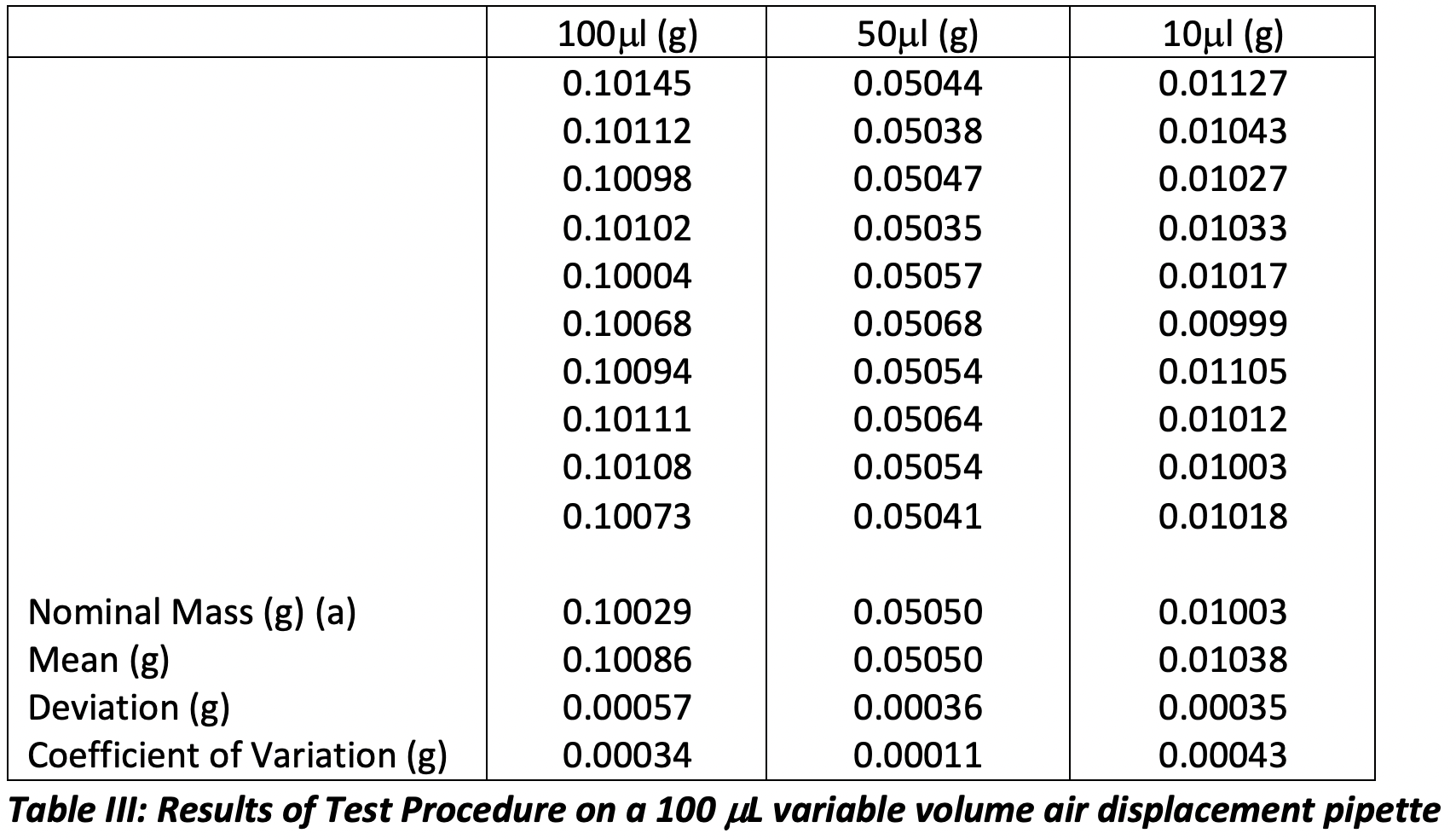
a – the mass of water is adjusted for the Z correction factor: temperature (20.5 oC) and pressure (1.010 kPa) in the laboratory at the time of measurement, taken from ISO 8655-6
So, it would appear that my technique is reasonable, and I have achieved a reasonable performance against the ISO requirements for each volume:
My Systematic Error +0.57 ml (100) / +0.36 ml (50) / +0.35 ml (10), ISO Systematic Error Limit ± 1.5 μl (mass to volume Z correction factor insignificant)
My Random Error +0.34 ml (100) / +0.11 ml (50) / +0.43 ml (10), ISO Systematic Error Limit ± 0.6μl (mass to volume Z correction factor insignificant)
It is worthy of note, however, that the error associated with dispensed volume at 10 mL would not have met the ISO tolerances had I used a pipette of nominal volume 10 mL. This perhaps suggests that one needs to be reasonable about the fraction of the nominal volume that one dispenses, and I know several laboratories who specify that pistons pipettes should not be used to dispense volumes less than 50% of the nominal volume for precisely these reasons.
I was also interested in finding out the magnitude of error associated with various aspects of incorrect pipetting technique. The ISO guidance suggests a wide range of estimated errors, some of which are shown in Table IV:
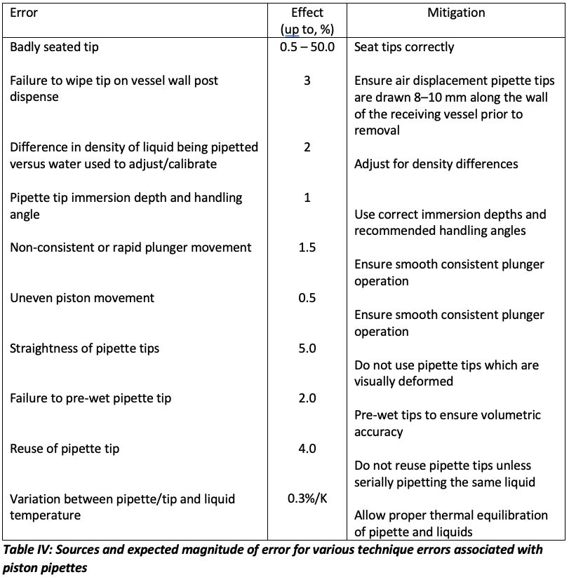
From Table IV, it is obvious that the total cumulative error associated with incorrect pipette technique can be very significant. I investigated the errors associated with some specific aspects of poor technique and these results are sown in Table V, all results are from 10 replicate measurements of 50 mL of water adjusted for the Z correction factor using a nominal 100 mL pipette.
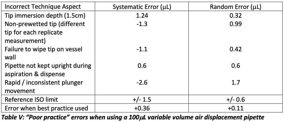
As can be seen from Table V, several of the poor techniques resulted in out of specification performance for the dispensed volume limits and all increased the inaccuracies relative to that obtained when using best practice. This is perhaps more salutary when considering that each error was implemented in isolation and that the cumulative error, if several of these poor techniques were combined, could be very considerable.
The reader will notice that I have made adjustments to the “expected” mass of water for these experiments in order to account for temperature and pressure differences between my local environment and the standard conditions used to calibrate (adjust) the pipettes (the Z correction factor). This takes me onto my final topic in this discussion, that of pipette testing and calibration, which I’m often asked about, typically by end users who wish to carry out verification between annual calibration and maintenance.
There are two procedures which are defined in ISO 8655-6:2002, the Test Procedure for more frequent “checking” of the accuracy and reproducibility of the dispensed volume and a Calibration Procedure which is typically carried out annually by the pipette manufacturer, although it should be said that this can also be carried out by the end user with a little experience and some basic metrology tools. While the full details of the Test and Calibration procedures are outside the scope of this article, I’d like to note several points which are poorly understood.
- Assessment of systematic and random error should be made on 10 replicate measurements
- Prior to measurement a tip should be wetted 5 times and then discarded to equilibrate the air within the pipette to temperature and relative humidity
- A new tip should be installed for each of the 10 measurements and each tip should be pre-wetted once before aspirating the required volume
- For measurements below 50mL an assessment of evaporation of the test liquid (water to ISO 3696) should be made by measuring mass loss over the same time period as the 10 test measurements and then dividing this mass loss by 10 and adding the resulting mass to each test weighing
- A correction for temperature and pressure (the Z correction factor) should be made for the mass of water to account for local conditions versus those for adjustment under standard conditions (tables of water mass at various temperature and pressure values can be found in ISO 8655-6)
- For variable volume pipettes, the assessment should be made at the nominal volume as well as 50% and 10% of the nominal volume (and all must conform to the ISO 8655-6 limits required for the nominal volume). Note here that the manufacturer may have separate tolerances for the nominal, 50% and 10% of nominal volumes.
- Systematic error is defined by the Variance of the 10 replicate measurements and Random Error by the Coefficient of Variation
I hope that this article acts to stimulate pipette users to examine their own practice and to guide them in best practice as defined by an international standards organization as well as the pipette manufacturers. I have certainly picked up many tips during the writing of this article, and I feel much more confident in my own ability to not only pipette more accurately with piston pipette devices, but also to sense when something is not right and to troubleshoot more effectively. To quote Henry Ford, “Anyone who stops learning is old, whether at twenty or eighty. Anyone who keeps learning, stays young.” I feel in the flush of my youth after this salutary learning experience!
Tony Taylor

Tony Taylor is the Chief Scientific Officer of Arch Sciences Group and the Technical Director of CHROMacademy. His background is in pharmaceutical R&D and polymer chemistry, but he has spent the past 20 years in training and consulting, working with Crawford Scientific Group clients to ensure they attain the very best analytical science possible. He has trained and consulted with thousands of analytical chemists globally and is passionate about professional development in separation science, developing CHROMacademy to provide high-quality online education to analytical chemists. His current research interests include HPLC column selectivity codification, advanced automated sample preparation, and LC–MS and GC–MS for materials characterization, especially in the field of extractables and leachables analysis.
New Study Reviews Chromatography Methods for Flavonoid Analysis
April 21st 2025Flavonoids are widely used metabolites that carry out various functions in different industries, such as food and cosmetics. Detecting, separating, and quantifying them in fruit species can be a complicated process.
Thermodynamic Insights into Organic Solvent Extraction for Chemical Analysis of Medical Devices
April 16th 2025A new study, published by a researcher from Chemical Characterization Solutions in Minnesota, explored a new approach for sample preparation for the chemical characterization of medical devices.

.png&w=3840&q=75)

.png&w=3840&q=75)


.png&w=3840&q=75)


.png&w=3840&q=75)

