The Evolution of LC Troubleshooting: Degassing
As chromatography technologies change, our approaches to using them in ways that value reliability, as well as the ways we should approach troubleshooting and fixing problems, should also change. In this installment, I continue the discussion started last month about how some specific troubleshooting topics have evolved over time, this time focusing on mobile phase degassing. Understanding how approaches to degassing have evolved is helpful for troubleshooting problems with pumps and detection, designing reliability into new methods, and when considering updates to legacy methods that have been in use for decades.
In recent months, I’ve been hearing from several readers of this column that they’ve appreciated the more educational, “back-to-basics” flavor of some of the “LC Troubleshooting” installments in the last year. So, last month I decided to dip a little further into that theme and provide some perspective on the evolution of various troubleshooting topics over the last few decades. My view is that this kind of perspective is particularly valuable to those who are relatively new to the field. There are some aspects of “the way we do things” that may seem peculiar on the surface, but are in fact very important to the reliability of high-performing liquid chromatography (LC) methods. On the other hand, some aspects of certain methods and ways of doing things are simply unnecessary in 2023 because LC technology has evolved in such ways that the old tricks aren’t needed anymore. Sometimes implementing the old tricks with new technology – though they provide no benefit – doesn’t do any harm, but they do add cost to analyses because they take time and resources to implement. Thus, we really ought to let them go if they are not adding any value to the method. In other words, let’s be smart about the methods we deploy. If we can’t come up with a better explanation for why something about the method is the way it is, then it’s time to let it go. In this installment, I will discuss the evolution of degassing in liquid chromatography. In general, degassing has become much more convenient, to the extent that most users probably rarely think about it anymore. However, some of the older techniques are still useful, and even with modern techniques it is useful to have a broad sense for how things have changed, as this can impact proper instrument operation when working with different generations of equipment. Readers interested in learning more details about the degassing topic are referred to previous installments of “LC Troubleshooting” (1,2), Dolan’s book on LC troubleshooting (3), and a very old, but very rich, paper by Bakalyar and coworkers (4).
Why Bother with Degassing at All?
In most applications, the biggest problem with gas bubbles inside of an LC system is that pumps generally don’t deal with the bubbles very well (see the last section below for other problems that can be significant in some applications). In the worst cases, a gas bubble can cause one or both of the check valves in a high-pressure pump to fail, causing a highly erratic flow or no flow at all. Where, then, do these bubbles come from? Although there are multiple mechanisms that can lead to bubble formation, the most practically relevant one in LC is the situation where two solvents are brought together to make a mixture (here, the mobile phase) that has a lower gas solubility than either of the individual solvents alone. This is most problematic with pumps that use the “low-pressure mixing” design. For a refresher on the differences between low-pressure and high-pressure mixing designs used in LC pumps, readers are referred to previous articles in this magazine (5). In the case of low-pressure mixing, the individual solvent components are brought together under nominally atmospheric pressure conditions before a high-pressure pump provides the force needed to push the mixture through the rest of the LC system.
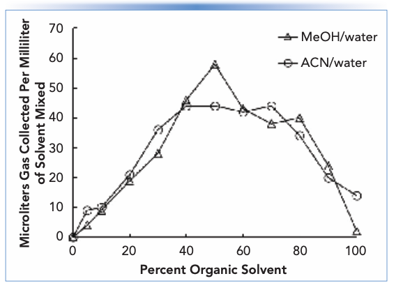
An example is valuable for illustrating the point here. The solubilities of oxygen gas at room temperature and atmospheric pressure in water or ethanol are about 0.3 × 10⁻⁴ and 5.7 × 10⁻⁴, respectively (4) (albeit on a mole fraction basis, meaning moles of oxygen relative to the total moles of oxygen and solvent). In other words, when saturated with oxygen, ethanol carries about 20 times more oxygen dissolved in the solvent compared to water. If we mix the two solvents in equal parts, then the amount of oxygen present in the mixture initially will be about 3.0 × 10⁻⁴ (mole fraction). However, the solubility of oxygen in a 0.5 (mole fraction) mixture of water and ethanol is only about 1.8 × 10⁻⁴ (mole fraction). This difference of 1.2 × 10⁻⁴ is the amount of oxygen in excess of the carrying capacity of the mixed solvent at saturation, and this excess will manifest in the formation of significant bubbles. In a low-pressure mixing pump, these bubbles will be drawn into the pump, and may cause failure of one or both check valves. So, in this example, avoiding the problem requires that the concentration of gas dissolved in each of the individual solvents is decreased prior to mixing such that the gas concentration in the mixed solvent (mobile phase) is lower than the solubility limit of the gas in that solvent. If this is achieved, then bubble formation will not be nearly as serious. A different way of thinking about the same problem is to consider the volume of gas that will be evolved as bubbles upon mixing of two solvents. Figure 1 shows data along these lines from the work of Bakalyar and coworkers (who physically measured the volumes of bubbles formed using an apparatus for trapping the bubbles) for mixtures of methanol or acetonitrile with water (4). We see that the volumes can be quite remarkable – 60 μL of gas per milliliter of mixed solvent! – and that these volumes roughly maximize around 50:50 mixtures of the organic solvent and water.
FIGURE 1: Gas evolved from different mixtures of solvents commonly used in reversed-phase LC. Adapted from (4).
The situation with pumps that use a high-pressure mixing design is quite different. In this case the mixing point for the mobile phase components is downstream from the high-pressure pump heads, and the pressure at which the mixing occurs will be nominally the same as the column inlet pressure (that is, well above atmospheric pressure). Under these conditions the gas solubility in the mobile phase will be much higher and bubbles will not form while the liquid is under pressure. However, as the pressure drops toward atmospheric pressure at detector, bubbles may form when the gas concentration reaches the solubility limit in the mixed solvent. If bubbles form in an optical flow cell (for example, ultraviolet-visible (UV-vis) or fluorescence), this can lead to unstable baselines, including spiking patterns.
Survey of Degassing Techniques, Old and New
Including older discussions of degassing techniques used in LC, the list includes: heating, sparging, refluxing, sonication, offline vacuum degassing, and inline vacuum degassing. I personally am not aware of anyone currently routinely using heating or refluxing for degassing, and I won’t discuss those approaches further here.
Sparging
I like to think of sparging as a technique that “scrubs” dissolved gases from a liquid. The principal fact in play here is that helium is much less soluble in LC solvents than other gases, including oxygen and nitrogen. In methanol, which is particularly problematic as discussed above, the solubilities of these three gases at room temperature and atmospheric pressure are about 0.7 × 10⁻⁴, 2 × 10⁻⁴, and 4 × 10⁻⁴ (mole fraction), respectively (4). To use the sparging approach in practice, helium is deliberately bubbled into a LC solvent. Other gases dissolved in the liquid diffuse into the helium bubbles and are carried out of the liquid as the helium bubbles rise to the surface. After an initial scrubbing period (15 minutes of sparging will remove about 80% of the oxygen dissolved in methanol [6]), the “gas-free” solvent can be maintained on the instrument with a very low flow of helium into the solvent bottle. Helium sparging has fallen out of favor due to the introduction of other approaches (mostly inline degassing, discussed below), practical inconvenience (nobody wants to deal with compressed gas cylinders if they don’t have to), and the cost of helium, meaning it is not commonly used today. That said, I do still have LC instruments in my laboratory that have the necessary plumbing and sparging stones to support this approach.
Sonication
A very simple approach to degassing is to simply place a bottle of solvent to be used on the LC instrument in an ultrasonic bath for several minutes before use. Unfortunately, this approach is not very effective; fifteen minutes of sonication will only remove about 30% of the dissolved oxygen dissolve in methanol (6).
Offline Vacuum Degassing
In the offline vacuum degassing approach, a vacuum is applied to a bottle containing the solvent that will ultimately be used on the LC. The most convenient and safe source of vacuum would be a house vacuum system, as found in many laboratories. The fundamental idea here is that reducing the pressure in the bottle decreases the solubility of gases dissolved in liquid, and any gas present above the solubility limit will spontaneously bubble out of the liquid. The vacuum can be applied using a sidearm type of flask with a hosebarb connection, or a plastic bottletop adapter with a hosebarb fitting that can be used to connect to the bottle to the vacuum source. When using this approach, great care should be taken to ensure that the container placed under vacuum is not physically compromised with cracks or other defects, as this could lead to a dangerous implosion of the container. Using a safety shield when the bottle is under vacuum is a good idea. Users should also be careful to use an explosion-proof vacuum pump if using a pump as the vacuum source, particularly when working with solvents that produce explosive vapors.
In my laboratory, we have found it most effective to combine offline degassing and sonication. The additive effects of the two approaches are both visibly obvious and unforgettable. As a demonstration, I suggest preparing a 50:50 mixture of acetonitrile and water, and placing the mixture under vacuum until no bubbles are observed. Then, while the bottle is still under vacuum, place the bottle in an ultrasonic bath. A vigorous rush of bubbles will be observed, and then completed within seconds. Although we only use inline degassing (see below) for routine degassing of solvents on LC instruments in my lab, the combination of offline vacuum degassing and sonication is still very useful in situations where a complementary degassing approach is needed. For example, if one suspects that the inline degasser in a pump is not working, and leading to bubble formation, degassing the solvent offline can enable a very informative test of the rest of the system to rule out the possibility that the inline degasser is the source of the problem.
Inline Vacuum Degassing
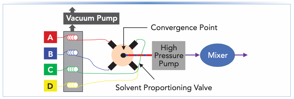
A simple block diagram illustrating the use of inline vacuum degassing in LC pumps is shown in Figure 2. In this approach, the solvent is drawn from the bottle through a polymeric tube situated inside of a vacuum chamber on its way to the inlet check valve of the pump (in the case of a high pressure mixing design) or a proportioning valve (in the case of a low-pressure mixing design). The polymer chosen for the tubing inside the vacuum chamber is one that is permeable to the major gases dissolved in the solvent that we need to remove (mainly nitrogen and oxygen), such that gas molecules are drawn across the tube and removed from the liquid selectively. Following the discovery in the early 2000s of particular polymers with enhanced permeability for these gases (7), inline vacuum degassing has become the dominant means of degassing used in LC instruments today. In general, it is easy to use (no manipulation by the analyst) and quite robust (except for an occasional vacuum pump failure or leaky fitting). One important aspect to keep in mind when using inline degassers is that molecules other than dissolved gases that are small and volatile can also cross the tubing wall and be swept away by the vacuum pump. When using pre-mixed solvents (that is, mixed in the solvent bottle so that a mixture such as methanol/water enters the degasser), this means that the composition of the solvent exiting the degasser module will be different from the composition of the solvent entering the module, due to preferential loss of the more volatile component of the solvent. For example, an acetonitrile/water mixture will contain a little less acetonitrile exiting the degasser than it did entering it. For most applications these changes will not be large enough to affect method performance, but some applications that are more sensitive to solvent composition may be affected. Similar effects on the solvent composition occur with other degassing methods, including sparging and offline degassing, so this is not a problem unique to inline degassing.
FIGURE 2: Block diagrams for a LC pump with a low pressure mixing design. The inline vacuum degasser is placed between the solvent bottles and the proportioning valve.
Tips and Other Details to Consider
Degasser Holdup Volumes
Older models of inline vacuum degassers relied on long lengths of less permeable tubing compared to the polymers used in newer models. A practical consequence of this is that the volumes of liquid inside older degasser modules (sometimes referred to as the holdup volume of the degasser) were much larger than they are now. This can be important for two reasons: 1) when working with a newer instrument, the analyst may not need to flush the degasser as long as they had to with an older module when changing solvents; and 2) conversely, when moving to work with an older instrument or an instrument from a different vendor, the degasser flushout time used when changing solvents may need to be adjusted to account for different holdup times. In every case, users should either consult the user manual for the particular model of degasser they are using to find out what the degasser holdup volume is, or a find a recommendation for the flushout volume for the degasser when changing solvents.
Effects of Dissolved Gases on Detection
In addition to the effect of dissolved gases on bubble formation and pump performance, these gases can also affect detection in LC. For example, Brown and coworkers showed that there can be a 400 mAU difference in the absorbance of methanol at 210 nm when the solvent is fully degassed compared to when it is saturated with air (6). Thus, if degassing efficiency varies over time, this variation can lead to detector baseline drift (long-term changes) or waves in the baseline (short-term changes). Moreover, Bakalyar and coworkers showed that changes in the level of dissolved oxygen in the mobile phase significantly affected the fluorescence signal for some analytes in an application focused on the quantitation of polyaromatic hydrocarbons (4). Here, variations in degassing efficiency could have significant effects on the quantitative performance of methods using fluorescence detection.
Summary
In this installment of “LC Troubleshooting,” I’ve discussed the importance of degassing solvents used for liquid chromatography, as well as older and newer approaches to the task. The primary problem that can be avoided with proper solvent degassing is bubble formation, which can cause erratic or even no flow from the LC pump. While inline vacuum degassing is currently the dominant approach used in commercially available instruments, there certainly are situations where older approaches, including sonication and offline degassing, are still useful. Understanding the history of these practices, and how they have evolved over time, is a useful facet of knowledge for aspiring LC troubleshooters.
References
(1) Dolan, J. W. Mobile Phase Degassing: What, Why, and How. LCGC N. Am. 2014, 32 (7), 482–487.
(2) Dolan, J. W. How Does It Work? Part II: Mixing and Degassing. LCGC N. Am. 2016, 34 (6), 400–407.
(3) Dolan, J. W.; Snyder, L. R. Troubleshooting LC Systems: A Comprehensive Approach to Troubleshooting LC Equipment and Separations; Humana Press: Clifton, N.J., 1989.
(4) Bakalyar, S. R.; Bradley, M. P. T.; Honganen, R. The Role of Dissolved Gases in High-Performance Liquid Chromatography. J. Chromatogr. A 1978, 158, 277–293. DOI: 10.1016/S0021-9673(00)89973-2
(5) Stoll, D. R. Mixing and Mixers in Liquid Chromatography – Why, When, and How Much? Part I, The Pump. LCGC N. Am. 2018, 36 (10), 746–751.
(6) Brown, J. N.; Hewins, M.; Van Der Linden, J. H. M.; Lynch, R. J. Solvent Degassing and Other Factors Affecting Liquid Chromatographic Detector Stability. J. Chromatogr. A 1981, 204, 115–122. DOI: 10.1016/S0021-9673(00)81646-5
(7) Sims, C.; Gerner, Y.; Hamberg, K. Vacuum Degassing. US6248157B1, June 19, 2001.
About the Column Editor
Dwight R. Stoll is the editor of “LC Troubleshooting.” Stoll is a professor and the co-chair of chemistry at Gustavus Adolphus College in St. Peter, Minnesota. His primary research focus is on the development of 2D-LC for both targeted and untargeted analyses. He has authored or coauthored more than 75 peer-reviewed publications and four book chapters in separation science and more than 100 conference presentations. He is also a member of LCGC’s editorial advisory board. Direct correspondence to: LCGCedit@mmhgroup.com


Common Challenges in Nitrosamine Analysis: An LCGC International Peer Exchange
April 15th 2025A recent roundtable discussion featuring Aloka Srinivasan of Raaha, Mayank Bhanti of the United States Pharmacopeia (USP), and Amber Burch of Purisys discussed the challenges surrounding nitrosamine analysis in pharmaceuticals.
Extracting Estrogenic Hormones Using Rotating Disk and Modified Clays
April 14th 2025University of Caldas and University of Chile researchers extracted estrogenic hormones from wastewater samples using rotating disk sorption extraction. After extraction, the concentrated analytes were measured using liquid chromatography coupled with photodiode array detection (HPLC-PDA).


