Health and Safety Concerns of Hydrogen Use with Gas Chromatography
I’ve had a few conversations lately with folks considering the switch from helium to hydrogen as a carrier gas for GC & GC–MS. Whilst the attitudes of laboratory staff to hydrogen use have evolved quite considerably, I do note that those of our Health and Safety (H&S) colleagues remain less so.
As I watch the faces of H&S representatives drop as I mention hydrogen gas being used in the laboratory, I often wonder if the laboratory staff have informed their colleagues that hydrogen is probably already used within the laboratory, unless you are running GC–MS with no flame ionisation, flame photometric or thermal conductivity detector. The absolute fact within the discussion regarding the use of hydrogen, is that the health and safety of laboratory workers should be the primary concern of everyone involved, and any use of hydrogen should be with the full involvement of our in-house safety experts. However, as more and more of us consider hydrogen as an alternative carrier gas to either combat supply chain issues or try to preserve helium as a natural non-renewable resource, it’s worth considering how to safely use hydrogen for chromatographic applications.
So, what factors should we all be considering when using hydrogen within the analytical laboratory, either as a make-up gas or as a carrier gas, and what precautionary measures need to be employed?
To frame our discussion, let’s first look at some of the relevant properties of hydrogen gas.
- Hydrogen is an odourless, colourless, and tasteless gas which is lighter than air. The diffusivity of hydrogen in air is 0.668 cm2/sec, which is around four times that of air in air and three times that of methane in air (1).
- Flammable concentrations of hydrogen in air are between 4% v/v and 75% v/v at atmospheric pressure (2).
- The ignition temperature of hydrogen/air mixtures is from 585 ºC (3).
- The Minimum Ignition Energy (MIE) of hydrogen at 20% v/v in air, is around 0.017 mJ. The MIE value rises rapidly (> 0.1 mJ) as concentrations fall below 10% (4). For comparison, the MIE of petrol vapour or methane at 20% v/v in air is >0.1 mJ.
- The detonation concentration of hydrogen in air at atmospheric pressure is between 18.3 and 59% v/v (5).
- Hydrogen flames are invisible.
Clearly, hydrogen is a laboratory gas that we must take very seriously. It is both flammable and explosive under some of the conditions outlined above. Rapid hydrogen escape can result in auto-ignition or detonation. There are reports available of incidents and accidents resulting from hydrogen use within a laboratory environment, but not necessarily with respect to the use for chromatographic applications (6–8). As such, we need to take the safe use of this very useful chromatography gas very seriously, and we can begin by considering its risks when used within the analytical laboratory.
Firstly, the gas is odourless and colourless; therefore, it is impossible for us laboratory workers to detect it organoleptically. Secondly, its low molecular weight and high diffusivity typically means that it will quickly diffuse to the top of its confining space, which could be the top of a GC oven or the laboratory ceiling.
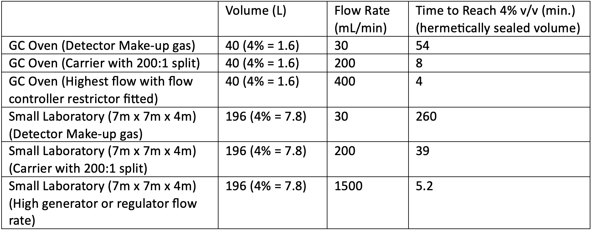
The important concentrations for hydrogen air mixtures are 4% for autoignition, 10% for ignition (typically spark ignition) and 18% for detonation. Let’s look at some relevant figures for reaching the worst-case scenario concentration (4% v/v) for hydrogen used at typical flow rates within gas chromatography, as well as some incident scenarios where a more rapid evolution of the gas may occur.
Table 1

The figures in Table 1 are a “worst case” scenario in many respects. I have considered a small laboratory and a GC oven, which has no safety precautions, and in both cases I have assumed that the volumes are hermetically sealed, i.e. no diffusion from the oven or room is possible. Given the inherent risks of hydrogen outlined earlier, we need to take precautions that the leak or gas release situations described in Table 1 are never encountered.
In practice, there are many safety features within the modern gas chromatography system which are deigned to either limit hydrogen escape, detect leaks, or minimize the opportunity for hydrogen accumulation. Most manufacturers include a flow limiting frit within the electronic gas pressure/flow regulation mechanism, which restricts the total flow of the gas through the device to a set level. Typically, the required frit porosity (and hence, the maximum gas flow) is chosen depending upon the application requirements and the gas being used. This feature guards against the possibility of a dual failure, such as the combined failure of the proportioning valve to seat properly and a column breakage at the detector end of the column. Most systems now have pressure setpoint detection, which first gives an audible or visual alarm prior to shutting the system down (gas flows and heated zones) if a pressure or flow set-point cannot be achieved within the system. This guards against all major leaks within the system, other than a column which breaks sufficiently near the detector that there is enough column flow resistance to maintain the carrier gas pressure setpoint. Should a leak occur into the oven volume, systems can be designed to give enough flex within the oven shroud or door that an explosion will cause these components to buckle or flex to relieve pressure, all without risk of being structurally compromised and emitting potentially harmful debris. In some systems, the oven cooling flap is designed to be left partially open during system shutdown, such that if there were a leak into the oven, the gas can diffuse readily into the laboratory atmosphere rather than accumulate into the oven volume. Systems may also run the cooling fan with the flap open prior to the initiation of oven heating to dissipate any accumulated gases from the oven following a shutdown or periods of inactivity. Some GC manufacturers offer hydrogen detectors which can be placed inside the GC oven, but these may also be acquired by third party providers. Hydrogen detectors may also be purchased for laboratory environment monitoring, and one should follow manufacturers’ installation guidelines carefully, as these units are typically installed higher up within the room due to the low density of hydrogen.
When using high split flows (in the order of 100–200 mL/min. or higher), one should be mindful that the split flow vent (outlet) may need to be evacuated outside of the laboratory using ducting or a localised extraction/exhaust system. One needs to work with manufacturers to ensure that any increased back pressure on the split vent outlet does not cause issues with the gas regulation of the carrier to the GC inlet. It is also important to consider the use of “gas saver” features, which ensure that the split flow is reduced to a low level at an appropriate time post sample injection when operating split injection mode.
Using hydrogen with GC–MS systems presents further issues for consideration. Hydrogen typically has higher linear velocity (or flow rate per column diameter) to take advantage of its inherently higher chromatographic efficiency and lower compressibility. It is therefore recommended that higher capacity vacuum pumps are used to avoid hydrogen accumulation in the spectrometer, as, due to its higher diffusivity and lower viscosity, it is inherently more difficult to pump away than either helium or nitrogen. This is particularly important, as the filaments used in the mass spectrometer ion source operate at very high temperatures and can act as an ignition source. Some manufacturers offer an inert gas venting system, such that if the vacuum system should fail, the carrier gas is immediately flushed from within the ion source and mass analyser using a separate flow of nitrogen or other inert flush gases. It should be noted that when restoring power to the mass spectrometer, you should ensure that all accumulated gas is vented from the mass spectrometer prior to the restart or using an inert gas purging system, if fitted.
In all cases, if a GC or MS system is shut down, or if a leak is suspected, one should turn off the hydrogen gas source (i.e., at the generator or cylinder pressure regulator) to ensure no further gas is supplied into the equipment or the laboratory environment.
We also need to consider the gas source when using hydrogen, which will usually be either gas cylinders or hydrogen generators, as well as the tubing which connects the gas source to the chromatographic equipment.
Leaving aside the actual gas being used, cylinders present a significant health and safety risk in terms of manual handling. We will need to ensure that any cylinders within the laboratory are properly secured into position and chained into the upright position, to prevent toppling and the potential for shearing of the regulator from the cylinder head. As a flammable gas, the cylinder head pressure regulators used with hydrogen have a left-hand thread to ensure the correct type of regulator is used. Snubbers or stoppers can be fitted to the regulator outlet and limit the outlet flow from the cylinder, should a catastrophic leak develop downstream from the cylinder. This is particularly important as release of large volumes of hydrogen at high speed can result in auto-ignition or detonation. The decision to locate the hydrogen cylinders either inside or outside the laboratory is often a difficult one. Positioning outside the laboratory clearly reduces hazards due to cylinders falling, exploding, or developing a catastrophic leak within an enclosed environment. However, this often means long lengths of tubing with connectors to reach the equipment, some of which may be inaccessible to leak check, or pass through confined spaces where a leak could result in a rapid increase of hydrogen concentration. To this end, the integrity of the gas supply lines and connections should be checked on a regular basis by undertaking a pressure drop test in which both the cylinder pressure regulator is closed and the GC is shot down, allowing the pressure decay on the outlet side of the cylinder regulator to be monitored in order to assess the decay rate when there is neither supply or demand on either end of the connective tubing. The higher the rate of pressure decay at the cylinder head pressure regulator, the higher the volume of gas escape in the connective tubing between the cylinder and the chromatograph.
Hydrogen is also known to “embrittle” certain metals, such as stainless steel, which reduces ductility, toughness, and tensile strength, sometimes to the point where cracking can occur. For this reason, copper or brass tubing, fittings and connectors are typically used between the gas source and the chromatograph, as they are known to resist these effects when used with hydrogen gas. It is particularly important to avoid stressing tubing or connections within the gas lines supplying the instrument; for example, be particularly careful when moving the GC on the bench to access the rear of the instrument or gas traps. Carefully pressure or leak check any connections or tubing which may have been moved or stressed prior to re-establishing gas flow. One should isolate the instrument from the primary source of the gas production prior to any movement of the instrument, which can be done by switching off the supply from the cylinder or generator.
Gas generators can present a safer alternative to cylinders for hydrogen supply and are available in a wide range of specifications to meet various pressure/flow demands. Typically, hydrogen is produced in the generator via the electrolytic decomposition of water using platinum electrodes and often incorporate a proton exchange membrane (PEM), which separates the electrodes and assists with hydrogen isolation from the other half-reaction products. Generators are convenient, as they reduce manual handling risks associated with cylinders, with the only required feedstock being purified (deionised) water, which is typically readily available within the analytical laboratory. Furthermore, the hydrogen is produced on-demand, and most generator units have only a small gas reservoir to meet the demands of the application, lowering the volume of stored hydrogen within the laboratory.
The following safety features may be built into your generator, but you should consult your manufacturer to identify which of these is incorporated and how to use them, or consider each of these features when selecting a generator provider:
- Forced air ventilation within the generator housing to minimise accumulation of hydrogen/air mixtures.
- Self-tests to check for leaks on power up or initiating hydrogen production mode following long periods of inactivity, which shut off hydrogen production if a leak is detected.
- Sensing of pressure/flow setpoint achievement and automated shut down if these cannot be achieved.
- Pressure sensing within the unit which will shut down the generator if an over-pressure is sensed–shut down typically takes the form of interrupting the current to the cell so that gas production ceases and a pressure relief valve is opened to reduce pressure within the hydrogen storage reservoir.
- Sensors to detector when the water reservoir is running low.
- Hydrogen detection feedback which senses a gas leak within the instrument or within the laboratory environment and shuts down hydrogen production within the generator.
I hope that this information helps to provide a balanced discussion on the safe use of hydrogen within the laboratory. However, you should form a risk assessment of your own operating situation. The adoption and use of hydrogen for gas chromatography is well established in many laboratories, who use it as a make-up gas for certain detector systems. It is increasingly being evaluated for use as a carrier gas where, especially when using split injection mode, flow rates will be somewhat higher. If you are an established user or someone considering using hydrogen in the laboratory for the first time, you should do so with the full involvement of both your health and safety colleagues & the instrument manufacturers, in order to ensure that risks are appropriately assessed and that all design and safety measures are incorporated during installation, operation and maintenance; not only that, but make sure that an emergency plan is devised and clearly communicated in the event that a major leak of gas is detected.
I should say in conclusion, that I have worked with hydrogen in GC applications for over 35 years and, so far, have had no health and safety issues.
References
(1) CRC Handbook of Chemistry and Physics 104th Edition. CRC Press, Taylor & Francis Group 2023. https://hbcp.chemnetbase.com/faces/documents/06_40/06_40_0001.xhtml (accessed 2023-07-01)
(2) Hord, J. Is Hydrogen Safe? National Bureau of Standards (NBS) Technical Note 690, U.S. Department of Commerce, Washington, D.C., 1976.
(3) ISO. ISO/TR 15916:2015(E):Basic considerations for the safety of hydrogen systems. International Organization for Standardization, 2015.
(4) Ono, R.; Oda, T. Spark ignition of hydrogen-air mixture. J. Phys.: Conf. Ser. 2008, 142, 012003.
(5) Office of Energy Efficiency and Renewable Energy. Hydrogen Safety. U.S. Department of Energy, 2023. https://www1.eere.energy.gov/hydrogenandfuelcells/pdfs/h2_safety_fsheet.pdf (accessed 2023-07-01)
(6) Silvey, J. Cause of Schweitzer Hall blast under investigation. Columbia Daily Tribune, 2010. https://eu.columbiatribune.com/story/news/education/2010/06/28/cause-schweitzer-hall-blast-under/21415266007/ (accessed 2023-07-01)
(7) Benderly, B. L. University of Hawaii lab explosion caused by inappropriate gauge. American Association for the Advancement of Science, 2023. https://www.science.org/content/article/university-hawaii-lab-explosion-caused-inappropriate-gauge (accessed 2023-07-01)
(8) Kemsley, J. Lab Safety: Postdoctoral researcher killed in explosion at Tsinghua University. C&EN 2016, 94 (1), 7. https://pubs.acs.org/doi/10.1021/cen-09401-notw3
About the Author
Tony Taylor is Group Technical Director of Crawford Scientific Group and CHROMacademy. His background is in pharmaceutical R&D and polymer chemistry, but he has spent the past 20 years in training and consulting, working with Crawford Scientific Group clients to ensure they attain the very best analytical science possible. He has trained and consulted with thousands of analytical chemists globally and is passionate about professional development in separation science, developing CHROMacademy as a means to provide high-quality online education to analytical chemists. His current research interests include HPLC column selectivity codification, advanced automated sample preparation, and LC–MS and GC–MS for materials characterization, especially in the field of extractables and leachables analysis.


Detecting Hyper-Fast Chromatographic Peaks Using Ion Mobility Spectrometry
May 6th 2025Ion mobility spectrometers can detect trace compounds quickly, though they can face various issues with detecting certain peaks. University of Hannover scientists created a new system for resolving hyper-fast gas chromatography (GC) peaks.
Altering Capillary Gas Chromatography Systems Using Silicon Pneumatic Microvalves
May 5th 2025Many multi-column gas chromatography systems use two-position multi-port switching valves, which can suffer from delays in valve switching. Shimadzu researchers aimed to create a new sampling and switching module for these systems.
New Method Explored for the Detection of CECs in Crops Irrigated with Contaminated Water
April 30th 2025This new study presents a validated QuEChERS–LC-MS/MS method for detecting eight persistent, mobile, and toxic substances in escarole, tomatoes, and tomato leaves irrigated with contaminated water.

.png&w=3840&q=75)

.png&w=3840&q=75)


.png&w=3840&q=75)


.png&w=3840&q=75)


