Performance Qualification of HPLC Instrumentation in Regulated Laboratories
LCGC North America
This article demystifies the qualification procedures and proposes a well designed, easy and simple set of experiments upon which to establish internal standard operating proceduresfor the complete qualification of HPLC instruments.
The generation of high-quality, reliable analytical data is grounded on three fundamental components: instrument qualification, method validation, and user training (1,2). For the pharmaceutical industry, these activities fall under cGMP/GLP regulations. Although the specific regulations can vary for the environmental or other industries, the principles remain the same.
The first of these, instrument qualification, is the focus of this article. A laboratory plan for analytical instrument qualification (AIQ) is a requirement for all cGMP/GLP laboratories. The pending USP guidance document <1058> (3) reflects the evolving accepted practices for the introduction and qualification of analytical instrumentation into the regulated laboratory environment.
Instruments must be maintained systematically and proven to be precise and accurate for their intended use on an ongoing basis (4,5). However, the specific qualification procedures are, appropriately, not predetermined by regulation. Instead, the laboratory management is responsible for developing a scientifically sound, risk-based plan for the periodic maintenance and qualification of their analytical instruments. Nonetheless, the approach is subject to FDA review.
A sound instrument qualification program should be both scientifically rigorous and straightforward to use. It must be sufficiently comprehensive to capture aberrant instrument performance, yet be rapid enough to promptly return instruments to service after the maintenance or repairs have been completed. Development of the standard operating procedures (SOPs) and testing materials for the qualification program can be a daunting, and sometimes confusing task. This article presents an approach that we have developed and trialed over many years, which provides a comprehensive, rapid performance qualification for high performance liquid chromatography (HPLC) instruments.
Who Should Perform the Qualification?
The proposed USP AIQ monograph <1058> states that, "Users are ultimately responsible for instrument operations and data quality. The user's group encompasses analysts, their supervisors, and organization management." It further states that:
"Users should also be responsible for qualifying their instruments, because their training and expertise in the use of instruments make them the best-qualified groups to design the instrument test(s) and specification(s) necessary for successful AIQ."
This view of user responsibility is shared by the FDA (6).
The AIQ Process
The AIQ process is often summarized as "The Four Qs" — that is, the design, installation, operational, and performance qualifications, referred to as DQ, IQ, OQ, and PQ. For a new installation, the instrument vendor often will be responsible for the IQ and OQ procedures, albeit under laboratory SOPs governing this operation. Depending upon the vendor, some abbreviated form of a system check also might be performed. Some vendors refer to this as a performance verification (PV). The exact procedures used will vary with each manufacturer. This IQ–OQ–PV process essentially is performed once per installation. Upon completion, responsibility for routine maintenance and periodic qualification is transferred to the user, even if outside contractors are employed for future preventative maintenance and service. Logically, because each instrument vendor has their own particular qualification routines, a master-level set of laboratory PQ testing protocols must be created to generate uniform performance data across the different brands of HPLC systems within the laboratory, while specifying measures that are required due to instrument maintenance, repair, or change. Such protocols must be consistent with the company's overall change control policy.
Table I summarizes the AIQ process and typical situations in which each stage might be applied. Specific choices will vary from laboratory to laboratory, and this is not purported to be a comprehensive plan for all contingencies. However, some rational, prewritten plan must exist to govern whatever procedures are decided upon.
Note that unlike the OQ, PQ testing is performed frequently, for many different events. System suitability of a particular method is not a substitute for a PQ, although its procedures might be incorporated into a PQ testing protocol. A system suitability is method specific, and serves a very different purpose than a full PQ.
OQ and PQ also have different purposes, although similarities often exist in tests used for these qualification steps. A distinguishing feature of the OQ is its focus on testing the individual instrument module, and often is driven by the manufacturer's design specifications. PQ testing on the other hand, is holistic, and documents the performance of the working system, which, thus includes both hardware and software issues.
This difference is reflected in the development of reasonable acceptance criteria. While OQ requirements are influenced by the design limits of each particular module, PQ acceptance criteria reflect the minimum acceptable performance levels required for all instruments of similar types in the laboratory. The assignment of reasonable, acceptance criteria can be one of the more difficult aspects of the entire PQ process. When available, acceptance criteria are taken from compendial or other official sources, for example, USP <621>. Otherwise, scientifically reasonable, defensible criteria are assigned.
A word of caution is in order here. Users sometimes will look to the specifications section of an instrument manual for acceptance values. In our experience, those values for wavelength accuracy, noise, stability, and so forth are instrument-specific. Moreover, they sometimes are obtained under ideal conditions that cannot be replicated easily in the laboratory. Assignment of such vendor-specific values to all laboratory instruments invites unwarranted testing failures. PQ testing is coming from the opposite direction, and seeks to define an acceptable performance level for all instruments in the laboratory. It is thus expected that most instruments will perform significantly better than the limits set by the PQ. Under that umbrella, the performance history of each individual instrument becomes its signature, and is of greater value than its absolute performance. The rationale for the assigned values for some of the acceptance criteria are discussed more fully in the "Results" section.
Logical and clearly written ongoing maintenance procedures are equally important to a successful PQ program. Selected tests from the suite of test protocols can be performed, depending upon the situation. For example, if a pump seal fails midway before the next scheduled preventative maintenance due to normal wear, it is not necessary to requalify the entire LC system. After investigation and documentation of the cause (and its impact on any data already generated), only the pressure leak check and flow rate requalification normally would be performed. A similar logic would be applied to lamp changes. As part of the root cause assignment for the failure however, the laboratory should review its preventative maintenance frequency, perhaps increasing it if such failures are common. On the other hand, relocation of the instrument to a new bench or adjacent laboratory would initiate a full PQ, plus updates to the logbook and database documenting the new location. Shipment of the instrument to a new location would be treated like a new installation, triggering the entire IQ–OQ–PQ process, and perhaps a DQ if warranted.
The definition of instrument portability must be explicitly addressed in the SOP. An example of this might be an HPLC system on a portable cart that is used periodically for LC–mass spectrometry (MS) work. Without a clear definition of portability in the relevant SOP, an overzealous auditor might conclude that rolling the instrument over to the mass spectrometer constitutes a move, requiring a requalification, as has happened to one of the authors on occasion. Clearly written SOPs are essential to anticipate and forestall such issues.
Development of a PQ Test Method
We have developed a suite of test methods to fully evaluate the instrument under realistic conditions, yet be as rapid and as automated as possible. These test solutions have proven to be chemically stable at room temperature for at least two years. We maintain all test components as a single, convenient kit, which includes the solutions, a prequalified base-deactivated PQ test column, test protocols, and validated Excel template for data analysis. This creates a closed, reproducible system, in which the only variable is the mobile phase. A system suitability solution is included to confirm proper mobile phase preparation and column performance. With this approach, the PQ test system becomes an independent, universal measuring tool that can be reproduced easily in any laboratory worldwide on any brand of instrument.
Table II summarizes the PQ test system components. These solutions can be prepared and qualified in the laboratory under NIST-traceable conditions, or can be purchased commercially in kit form. The mobile phase stability is 60 days, so that it can be prepared in large batches and stored for multiple instrument qualifications.
The retention time window for caffeine is set at 1.0–1.5 min. A comprehensive isocratic qualification for all test protocols requires about 50 injections and is completed in as little as 1.5 h. Additional gradient qualification requires about 35 min for a binary system, or 65 min for a quaternary. Selected partial qualification test protocols such as autosampler precision and pump stability are completed in less than 30 min. Detector wavelength accuracy, column oven, refrigerated autosampler temperature accuracy, and flow-rate verification are manual operations. The remaining qualification tests are completed within a single injection sequence. Only three methods are required; one of 3-min length for the resolution test mixture and system suitability testing, a second method of about 1.8 min for the bulk of the test injections and a gradient method (if applicable) for dwell volume and accuracy determination.
Experimental
Acetonitrile was HPLC grade, purchased from EMD (VWR, West Chester, Pennsylvania). Water was purified in-house, meeting USP reagent-grade specifications. Caffeine, uracil, theophylline, and 8-chlorotheophylline were ACS reagent-grade or better, and were purchased from Sigma-Aldrich (St. Louis, Missouri). The certified PQ test column, 75 mm × 4.6 mm, Cogent C8, 5-μm particle size, was obtained from MicroSolv Technology Corporation (Eatontown, New Jersey). The mobile phase was filtered and degassed using a 0.45-μm nylon filter.
A validated Excel template was used for calculations and graphing. The template required only entry of the raw data, with all subsequent calculations and graphing being performed automatically by the spreadsheet. In addition to detailed results and graphs, the spreadsheet provides a single-page summary sheet for review and signoff.
For flow accuracy and leak-testing, a device was constructed from a back-pressure regulator with a qualified pressure gauge. A Tescom (Elk River, Minnesota) model 26-1721-24-084 back-pressure regulator was used, with a rating of 10,000 psi. Appropriate tubing and male-unions were fitted, so that the column inlet tubing could be connected to the union. Dyna-seal variable stop depth fittings were supplied by Sonntek (Upper Saddle River, New Jersey) to ensure secure leak-tight fittings without regard to stop-depths. The principle author can be contacted electronically if further details regarding construction of this device are required.
In practice, the back-pressure regulator assembly is fitted in lieu of the normal column. Any desired back pressure is applied by the regulator knob of the back-pressure regulator, at any flow rate. Flow accuracy measurements at various flow rates are made at a constant 1000 psi backpressure. The HPLC pressure readout is checked against the gauge at increments of 1000 psi, up to the maximum instrument pressure, typically just under 6000 psi. This back-pressure regulator system has proven to be an extremely useful and versatile tool to have available in the laboratory. It is used to diagnose pump check valve problems by observing pressure fluctuations. It has proven robust enough that it also can be used to perform leak checks, such that the system can be pressurized at any desired level, and the rate of pressure loss directly observed on the gauge.
Chromatograms in the figures were produced using an Agilent 1100 diode array system (Santa Clara, California) with a quaternary gradient. The flow cell was the standard analytical cell.
The test kit used in this article, complete with column, solutions, SOPs, and validated software, is available commercially from MicroSolv Technology Corporation as the High Speed Qualification (HSQ) kit.
Results and Discussion
Once the laboratory SOPs have been written and approved, and the instrument methods and sequences assembled, routine PQ testing is quite straightforward. The following shows typical results for some of the test protocols, along with a discussion of acceptance criteria.
Manual operations — pump accuracy, column oven temperature: Pump flow accuracy and stability are the foundation upon which the subsequent testing is built, because gradient dwell volume and other tests will use this value in their calculation. Most laboratories use dry volumetric flasks of different volumes, with a NIST-traceable calibrated stopwatch to measure flow rates. We use our back-pressure regulator system (see Experimental) to impose a constant pressure of 1000 psi, and measure the flow rates at nominal settings of 0.5, 1.0, and 5.0 mL/min. The qualification flow range should encompass all methods in the laboratory and can be modified as desired. Given the potential errors in drop collection and timing, an accuracy specification of ±5% is assigned for this test.
Column oven temperature is measured by using a NIST-traceable digital thermometer, inserting a flexible thermocouple into the compartment, taking care not to allow it to rest on any metal supports. The air temperature is measured over a temperature range encompassing all laboratory methods, with acceptance criteria of ±5 °C.
Column oven designs vary widely in their preheating designs and efficiency, and the actual mobile phase temperature might deviate substantially from the oven air temperature. There is simply no easy way to measure accurately the true internal column fluid temperature, which will vary with both radial and axial position within the column due to frictional heating (especially for ultrahigh-pressure LC), and other issues. In a similar vein, refrigerated autosamplers also are qualified using air, rather than solution temperatures, to the same specification.
Wavelength Qualification
The qualification of wavelength accuracy is a critically important test. Holmium oxide solution in 10% perchloric acid (NIST SRM 2034) is an internationally accepted wavelength standard, covering the range of 241–641 nm. Caffeine is used as a secondary standard, with two bands at 205 and 273 nm, in this diluent. Thus, both standards can be used in combination to qualify the detector over the range of 205–641 nm (or to 361 nm for the UV range only). The wavelength accuracy specification is set at ±3 nm, in accord with USP <621> (7).
Both variable-wavelength and diode-array detectors can be qualified by first autozeroing the detector with diluent in the flow cell, then pulling the solutions through the cell with a spring-loaded syringe and tubing, with a finger-tight fitting securing it to the detector outlet (never attempt to push the solutions, for safety reasons). Release the vacuum before testing to eliminate bubbles and produce a stable signal. For diode-array detectors, a spectrum of the flow-cell contents is taken, and the maxima are determined with the resident instrument software. While there are 14 available bands for holmium oxide, it is only necessary to measure three or four of these over the spectral region of interest (UV, visible, or both). For variable wavelength instruments, the wavelength is set sequentially in 1-nm increments, for a few nanometers before and after the absorbance band of interest. The absorbance reading is recorded, and the wavelength maximum found by interpolation. Alternatively, a series of no-injection, no-flow methods can be written, each with a different wavelength, stepping across the spectral region to find the maximum. Figure 1 shows the holmium oxide spectrum. For the UV range, the 241-, 287-, and 361-nm bands are convenient, while the 451-, 537-, and 641-nm bands can be added for visible-wavelength detectors.
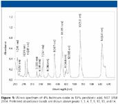
Figure 1
The found absorbance maxima are compared against the official published NIST values (8). The consensus spectral values are published for spectral bandwidths of 0.1, 1.0, and 3.0 nm. For most HPLC detectors, comparison against the 3.0 nm spectral bandwidth would be appropriate.
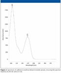
Figure 2
Figure 2 shows the spectrum of caffeine in the method diluent, used to extend the qualification to 205 nm. Note that the 273 nm maximum overlaps with the holmium oxide spectral range, thus, linking it to the NIST standard values. These spectral maxima have been confirmed independently to be accurate with this mobile phase and diluent (9). For diode-array systems, the caffeine spectrum can be acquired conveniently during the main injection sequence from of any of the mid-concentration solutions producing a good signal-to-noise ratio (S/N). Figure 3 shows the combined results for a typical wavelength accuracy determination using the combined results of both the holmium oxide and caffeine solutions, as automatically generated by the validated software. The slope of the regression should equal one, with a statistically nonsignificant intercept. While not used for qualification purposes, the regression line can be extrapolated to 200 and 700 nm, to show any inaccuracy trends at wavelengths outside the qualification range.
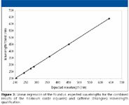
Figure 3
The combined solutions, with their narrow absorbance maxima across a wide wavelength range, produce what is currently a state-of-the-art wavelength accuracy qualification. However, some laboratories might have methods that use wavelengths falling outside of this range. The question frequently arises as to whether it is valid to use a method beyond the qualified wavelength range of the detector. Some feel that if a method of say, 200 nm is used, that the detector qualification must include that wavelength. The other view is that if the wavelength accuracy is confirmed at several points across a broad region of the spectrum, the detector can be presumed to be in reasonably good operating condition and is, thus, qualified for use across its entire wavelength design range. We support this second view.
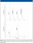
Figure 4
In support of this argument, note that for UV–vis spectrophotometer wavelength qualifications, most compendial agencies (including the USP, BP, and EP) specify holmium oxide as a suitable wavelength reference standard, with its limited range of 241–641 nm. None of these agencies state that a spectrophotometer cannot be used beyond this qualified range, which would be the inference from the first approach. By confirming operation at several discrete wavelengths across a broad swath of its design range, one assumes that the instrument will function as designed across its entire range. This is an assumption, but it is not unreasonable. Indeed, even within the qualification wavelength range, there is no proof that the monochrometer is not malfunctioning at some particular wavelength between the checkpoints. The system suitability of each method run on the instrument is designed to provide such additional run-time assurance of the system performance.
Isocratic HPLC Qualification
System suitability, noise, and extracolumn dispersion: Once the wavelength qualification, flow accuracy, and column oven temperature checks have been completed, all remaining tests are accomplished by a single fully automated injection sequence on the HPLC system. Figure 4 shows typical injections of the resolution test mixture solution, along with the (L3) caffeine solution (also containing uracil) used for injector precision and pump flow stability. A system suitability test is performed to demonstrate correct retention times and column efficiency and that the instrument is operating properly and ready to perform the required test protocols.

Table I: Components of the AIQ process over the typical laboratory instrument life-cycle
Dynamic noise: Short-term dynamic noise is determined for a blank injection at the method wavelength of 273 nm, thus, documenting total instrument noise levels under realistic operating conditions. Because all method conditions are constant, this noise value can be compared to historical levels for the same instrument, as well as to other instruments in the laboratory. A minimum S/N ratio of ≥10 is required for the L1 peak (generated in the method injection sequence), which is 0.1% of the highest concentration solution. Unusually high noise levels can indicate a failing lamp, a dirty flow cell, pump noise, or other problems. The noise values given by the manufacturers in their instrument specifications are usually for the detector alone under ideal conditions that cannot be replicated easily in the laboratory. Such a specific noise measurement might be performed as part of the OQ when an instrument is first put into service. The dynamic procedure described here has the advantage of providing a realistic noise measurement under standardized operating conditions, so that various laboratory HPLC systems can be compared directly. Note that the detector–data system time constant affects the noise and, thus, should be documented as part of the run method.
Extracolumn dispersion: Extracolumn volume dispersion results in the loss of sharpness of the eluted peak due to the injector, connecting tubing, and flow cell. It is the limiting parameter that determines whether small-particle, low-volume columns can be successfully used in a given instrument. It is not recommended that an acceptance criteria for extracolumn dispersion be part of the PQ. However, it is a very useful instrument characteristic to know, and should be documented during the course of the PQ.
The most accurate way to measure extracolumn dispersion is to measure the dispersion with a series of jumper tubes in lieu of the column, and extrapolate to zero length. However, a simpler, yet sufficiently accurate way is to plot the peak variances against the square of the retention volumes (10) as follows.
Because variances are additive, the observed total system variance is

The variance in volume units is calculated from the retention volume and the measured peak efficiency as follows:

The retention volume is simply the flow rate times the observed retention times for the resolution test mixture peaks, thus

where tR is the retention time (in minutes) of the peaks in the resolution test mixture (assuming the extracolumn volume delay is negligible relative to the peak retention times), F is the flow rate (as microliters per minute), and Nsystem is the measured efficiency for each peak. Regression yields an intercept of the extra column dispersion (σ2ec ) in units of μL2 (mm6 ) with a slope of the reciprocal of the true column efficiency, exclusive of extracolumn effects. The test mixture was designed specifically to match the dispersion levels found in modern analytical HPLC systems. Figure 5 shows a typical plot for determination of extracolumn dispersion. The extracolumn dispersion data is obtained from the injection of the Resolution Test Mixture, shared as part of System Suitability. Because the test conditions are defined and limited, and peak tailing due to the column is tightly controlled, this method yields sufficiently accurate dispersion values even when using the USP half-height or tangent efficiency techniques. These dispersion values usually differ by only a few microliters as compared with the more rigorous statistical moment efficiency method. The volume standard deviation (simply the square root of the volume variance), often is used as a more convenient term for the extracolumn dispersion produced by an instrument, and is sometimes misleadingly referred to as extracolumn volume. It is the volume dispersion that is being measured, not the physical volume of the connecting tubes.
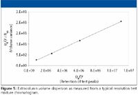
Figure 5
The greatest value of this test is the comparison of relative dispersion levels of various instruments within the laboratory, as well as deviations from the historical norms established for a single instrument. The range of measured extracolumn dispersion for six different analytical HPLC systems from three vendors is summarized in Table III.
Note that the dispersion can vary significantly even for two instruments of the same design, due to differences in the connecting tubing and instrument setup. While extracolumn dispersion measurements should be considered accurate only to 1–2 significant figures, they are still very informative. For example, only the first instrument would be even marginally compatible with the newer 1.8-μm particle columns (assuming 10% loss for a peak at k' = 1). Instruments 1–3 would be suitable generally for 3–μm columns of at least 3 mm diameter and moderate length, while instruments 4–6 should be restricted to conventional 5-μm or greater column technology.
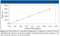
Figure 6
The extracolumn dispersion measurement is not part of the written PQ requirements in our laboratories and, thus, no formal acceptance criteria are assigned. However, the value is recorded in the instrument logbook and pasted onto the instrument face, along with other critical performance data, to facilitate rapid comparisons between instruments within the laboratory. It is a very useful parameter to have available when transferring methods to other laboratories or to troubleshoot problems for a given instrument, for example if large diameter tubing were substituted in some part of the critical flow path, or a semipreparative flow cell was mistakenly left in a detector, without proper documentation in the logbook.
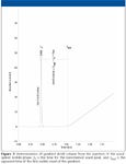
Figure 7
Detector linearity: Linearity of response across at least three orders can be expected for most modern HPLC detectors (USP <621>) and is necessary for single dilution purity methods at the 0.1% concentration level. The six caffeine solutions with concentrations from about 0.00035 to 0.35 mg/mL are designed to produce peak heights falling within the linear range of most modern HPLC detectors, using the typical 10-mm pathlength for an analytical flow cell. The entire absorbance range can be shifted up or down to produce the desired absorbance for different flow cell volumes or instruments, by adjusting the nominal injection volume to produce the desired response range. Each solution is injected in triplicate. Linear regression analysis is performed on the entire data set of 18 injections. A typical detector linearity plot is presented in Figure 6. Not shown is the plot of the residuals, which is printed along with the linear regression, to help illuminate nonlinearity.
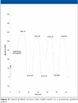
Figure 8
Injector carryover: Immediately following the last injection of the highest concentration (L6) standard, we inject blanks of clean mobile phase. Any detectable peak at the retention time of caffeine is the result of injector carryover. The percent carryover is calculated readily as the area of the carryover peak divided by the average of the L6 solution area. It should be noted whether a wash vial is used or not. We typically inject three blanks, using the first to calculate carryover. The remaining two serve to document how quickly the injector is able to cleanse itself if carryover is observed.
The instrument manufacturer's specifications should be consulted when setting the acceptance criteria for this test. A maximum carryover of ≤0.1% is common. However, this represents fairly substantial carryover, and in most cases, values of under 0.05% should be expected from a well designed autosampler in good repair. Excessive carryover can be caused by worn rotor or needle seals, although instrument design also plays a large role.
Autosampler volume linearity (optional): If the autosampler is capable of variable injection volumes, the linearity and precision of volume delivery across a range can be used as a general indicator of the condition of the autosampler delivery syringe and seals. Because the linear range of the detector already has been established, the volume delivery of the autosampler can be measured by selecting a test solute concentration that will produce peak areas falling within the established detector linear range. Using the L2 caffeine solution (0.0035 mg/mL), injections from 5–100 μL will produce peak heights and areas within this demonstrated range. These volumes can be modified to cover the injector design range. The L2 solution is injected in triplicate at each of five volumes covering the injector volume range. Linear regression is performed as previously shown for the detector linearity. In addition to good linearity, a nonsignificant intercept within the 95% CL is expected.
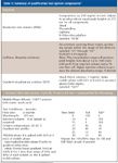
Table II: Summary of qualification test system components*
Gradient qualification — dwell volume and delivery accuracy: Gradient qualification consists of measuring the gradient dwell volume, the shape of a short linear gradient, and the delivery accuracy at 10% and 90% of each fluid combination. This is accomplished by spiking one of the mobile phases with the nonretained uracil (fluid circuit B is used in this illustration), to produce a mid-range absorbance signal at 273 nm (see Table II). An aliquot of this spiked mobile phase is injected, starting the gradient with no delay time.
A single gradient method is written, consisting of an initial 10-min linear gradient from 0 to 100% B. After a 5-min hold at 100% B to establish the maximum signal height, delivery accuracy is measured at 10% and 90% of each combination of the other fluid circuits with the spiked B circuit, using a 3-min hold at each level. The hold times can be varied if required to produce stable signals at each level.
To start the qualification, an aliquot of the uracil-spiked mobile phase is injected and the gradient profile is started. The uracil is eluted in the column void volume, while the onset of the gradient begins later, delayed by the gradient dwell time. The dwell volume is calculated using the previously calibrated pump flow rate, multiplied by the delay time. An example of a dwell volume determination is shown in Figure 7.
Figure 8 shows the full chromatogram of a typical gradient qualification profile for a quaternary gradient system.
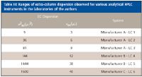
Table III: Ranges of extra-column dispersion observed for various analytical HPLC instruments in the laboratories of the authors
This general technique based upon uracil offers several significant advantages over using a jumper tube in lieu of a column. First, this procedure measures the operation of the entire gradient HPLC system under actual operating conditions of pressure and flow with a column in place. Second, the entire procedure is fully automated, and can be programmed as part of the overall PQ injection sequence, so that no manual substitution of jumper tubes is required. It is simple, and the steps of 10% and 90% delivery for each solvent combination adequately test the system near the extremes of its solvent delivery and mixing system. More-complex profiles can of course be generated if desired.
No acceptance criteria are assigned to the gradient dwell volume, because this is a design feature of each particular instrument. However, it is a critically important parameter to know for a gradient instrument (11,12) and its value is recorded in the logbook, and noted on the face of the instrument. For critical gradient methods, certain instruments might need to be flagged as being not suitable if they produce excessive dwell volumes or indistinct gradient profiles. During method development and validation, instruments with different gradient dwell volumes can be selected deliberately for robustness testing. During method transfer and troubleshooting, the gradient dwell volume of the receiving laboratory should be noted.
The general shape of the initial linear segment is documented, but no quantitative acceptance criteria are applied. For the delivery accuracy, an acceptance criterion of ±1% absolute is used, (equivalent to ±10% relative of the lower delivery range).
Table IV summarizes the test protocols that have been discussed previously, along with typical acceptance criteria.
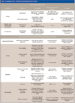
Table IV: Suggested HPLC performance qualification tests criteria
Final documentation: If any of the PQ tests fail, an investigation is initiated, and the cause of the failure is determined and corrected before retesting, as per our internal SOPs. After qualification, the summary results are entered into the laboratory database. We also affix to the instrument a brief tabular summary of the actual values obtained from the qualification, such as the dynamic noise, extracolumn dispersion and gradient dwell volume, in addition to the normal qualification sticker. This way, the performance of the various HPLC systems in the laboratory can be compared readily, as can changes in the performance of a given instrument compared to its historical record. This information can be extremely valuable when selecting instruments for intermediate precision, and of course when comparing instruments during method transfer and similar activities.
Conclusions
Implementing a comprehensive HPLC instrumentation maintenance and qualification program is a cGMP requirement. The use of a standardized PQ test system, complete with a prequalified column, greatly facilitates the routine testing of laboratory HPLC systems. The test system has been designed to be robust, while providing fast separations to reduce overall time to perform a qualification. A comprehensive suite of test protocols can be completed within a few hours. Having such a simple, yet universal test system available in the laboratory has many advantages:
In-house instrument qualification: The most obvious advantages of using an in-house performance qualification system are those of quality, time and money. In our experience, HPLC qualifications are often of higher quality when performed by trained laboratory personnel. Not only does the laboratory develop an intimate feel for the operating characteristics of each of its HPLC systems, but more time can be taken to investigate small aberrations in performance. With clear, well written SOPs, routine PQs can be completed within hours, at a large cost savings, with the added flexibility of being able to complete instrument testing on the laboratory's schedule rather than the instrument vendor's schedule.
Trending the performance of a single HPLC instrument: A major advantage of using a standardized test method for HPLC qualification is that one can obtain trends in the historical performance record of a single HPLC system. The accumulated performance history of each HPLC system is readily available, and any changes in the instrument performance such as after repairs or moving to a new location (precision, noise, efficiency, sensitivity) are immediately obvious.
Comparison of HPLC performance laboratory-wide and worldwide: A standardized, complete PQ test system permits direct comparison of the critical performance characteristics of all HPLC systems with and between laboratories under identical test conditions, so that valid comparisons of performance can be made between instruments. This information can be useful when selecting equivalent (or nonequivalent) instruments for robustness evaluation during method validation.
Instrument and method troubleshooting: If a problem is suspected during routine instrument operation, a quick PQ test will readily distinguish whether the problem lies with the test method, the user's understanding of the method or the instrument performance itself. If the test solutions are maintained in the laboratory, instrument problems often can be isolated quickly, saving weeks of troubleshooting and reducing unnecessary travel to remote sites.
Method transfer: Before method transfer, the recipient laboratory anywhere in the world can test their HPLC conditions identical to the originating laboratory. In the event of method transfer problems (which can be common), instrument performance characteristics (gradient dwell volume and delivery accuracy, injector precision and carryover, noise, sensitivity, and so forth) can be compared for equivalency and suitability before transfer. For method troubleshooting, one can go back quickly to the PQ conditions to rule out instrumental problems.
Training: This test system also makes an excellent training and evaluation tool for analysts new to HPLC. The analyst is given the materials and procedures in the kit, using an instrument that has been previously qualified, and is instructed to make the mobile phase and run the various test protocols. Because the separation and the quality of the expected data are already known, the new analyst becomes the unknown. This exercise can help the student learn all aspects of the operation of the instrument under both isocratic and gradient conditions, including how to use the data system and select suitable integration parameters, as well as proper preparation of the mobile phase and column installation.
Ensuring and documenting the quality of analytical data is a fundamental responsibility of all analytical laboratories. Instrument qualification is one of the basic components required to achieve this goal. Even if preventative maintenance is contracted to an outside vendor, final qualification by in-house personnel is highly recommended. The accumulated historical data acquired under universal test conditions becomes a very strong pillar, complementing method validation, and training.
Acknowledgments
The authors would like to thank Mr. Frank Harris of Vintage Pharmaceuticals, Inc., and Mr. Nilesh Patel of Actavis Pharmaceutical Company for their input and assistance.
References
(1) H. Lam, in Analytical Method Validation and Instrument Performance Verification, C.C. Chan, Y.C. Lee, H. Lam, and X.M. Zhang., Eds. (Wiley-Interscience, Hoboken, New Jersey, 2004), pp. 173–185.
(2) J. Crowther, M.I. Jimidar, N. Niemeijer, and P. Salomons, in Analytical Chemistry in a GMP Environment, J.M. Miller and J.B. Crowther, Eds. (Wiley-Interscience, New York, 2000), pp. 423–458.
(3) United States Pharmacopeial Forum, Vol. 32(2), pp. 595–605, <1058>, Analytical Instrument Qualification, Mar.–Apr. 2006.
(4) V. Grisanti and E.J. Jachowski, LCGC 20(4), 356–362 (2002).
(5) G. Hall and J.W. Dolan, LCGC 20(9), 842–848 (2002).
(6) W.B. Furman, T.P. Layloff, and R.F. Tetzlaff, http://www.fda.gov/ora/science_ref/priv_lab/comp_liq_chro/jaoac.htm.
(7) United States Pharmacopeia, Chapter <621>.
(8) J.C. Travis, J.C. Acosta, G. Andor, J. Bastie, P. Blattner, C.J. Chunnilall, S.C. Crosson, D.L. Duewer, E.A. Early, F. Hengstberger, C.S. Kim, L. Liedquist, F. Manoocheri, F. Mercader, L.A.G. Monard, S. Nevas, A. Mito, M. Nilsson, M. Noel, A.C. Rodriguez, A. Ruiz, A. Schirmacher, M.V. Smith, G. Valencia, N. van Tonder, and J. Zwinkels, J. Phys. Chem. Ref. Data 34(1), 41–56 (2005).
(9) S. Tomellini, Univ. Of New Hampshire, private communications.
(10) K.W. Freebairn and J.H. Knox, Chromatographia 19, 37–47 (1985).
(11) L.R. Snyder, J.J. Kirkland, and J.L. Glajch, in Practical HPLC Method Development (Wiley, New York, 1997), pp. 386–394.
(12) J.J. Gilroy and J.W. Dolan, LCGC 24(7), 662–668 (2006).
Polysorbate Quantification and Degradation Analysis via LC and Charged Aerosol Detection
April 9th 2025Scientists from ThermoFisher Scientific published a review article in the Journal of Chromatography A that provided an overview of HPLC analysis using charged aerosol detection can help with polysorbate quantification.
Removing Double-Stranded RNA Impurities Using Chromatography
April 8th 2025Researchers from Agency for Science, Technology and Research in Singapore recently published a review article exploring how chromatography can be used to remove double-stranded RNA impurities during mRNA therapeutics production.


