The Perfect Method, Part VI: Make it Faster
LCGC North America
In the previous installments of this series on efficient development of LC methods (1?5), we have concentrated on improving resolution by modifying the mobile phase, choosing a different stationary phase, or changing some other condition, such as column temperature. In this month?s "LC Troubleshooting" installment, we take a look at trading some of that resolution for a faster separation.
Who doesn't want more speed? Whether you are looking at a new motorcycle, examining your times for a 10K run, or developing a liquid chromatography (LC) method, faster usually is better. Face it, most of us who work as chromatographers get paid, either directly or indirectly, by the number of samples we run. A faster method allows us to run more samples or get the sample set done more quickly so we can move on to something else. In the previous installments of this series on efficient development of LC methods (1–5), we have concentrated on improving resolution by modifying the mobile phase, choosing a different stationary phase, or changing some other condition, such as column temperature. In this month's "LC Troubleshooting" installment, we're going to look at trading some of that resolution for a faster separation.

John W. Dolan
One More Time
Throughout this series on efficient LC method development we have been using equation 1 as a guide. Usually our goal (1) is to develop a method that gives baseline resolution, Rs, for all components of interest. If it is to be a method used under the oversight of one of the regulatory agencies, Rs > 2.0 is recommended. As a starting point (2), we chose a reversed-phase C8 or C18 column, because this chromatographic mode has a high probability of success with most samples. A 150 mm × 4.6 mm column packed with 5-μm diameter particles or a 100 mm × 4.6 mm, 3-μm dp column was used, because these columns generate approximately 10,000 theoretical plates, N, which is sufficient to separate most sample mixtures. As a bonus, these column sizes can be run at 1.5–2.0 mL/min for a reasonable run time without much concern about excessive pressure.

As soon as we had our starting conditions, we worked our way through equation 1 in an effort to develop a separation with the necessary resolution. First we tried adjusting the retention factor, k, which is most easily controlled by changing the mobile phase strength (3). We started with a strong mobile phase, such as 90:10 acetonitrile–water (or buffer) or methanol–water, then worked in a step-wise fashion to weaker mobile phases (more aqueous phase) until k was in the 1 < k < 20, or better 2 < k < 10, region. Because a change in k also results in a change in selectivity, α, for many sample mixtures, adjustment of the mobile phase strength may be enough to obtain the required resolution. If mobile phase strength changes are not sufficient, we can add more power to the process by concentrating on α through adjustments in the chemistry of the mobile phase (4) by changing solvents from acetonitrile to methanol (or vice versa), or changing the pH, temperature, or mobile phase additives. Selectivity also can be changed with a change in the column packing type (5), although this option often is reserved for later in the development process, because of the expense of purchasing additional columns.
At this point in the process, we hopefully have the resolution we need through the adjustment of k and α using a column that generated a sufficient number of theoretical plates. If the resolution is satisfactory and the run time is acceptable, we should be ready to validate the method. If resolution is larger than is needed, we can trade some of that resolution for shorter run times. If resolution is smaller than is needed, we may be able to adjust N to gain a little resolution.
The Column Parameters
I like to refer to the factors that influence only N, without a change in selectivity, as "column parameters." These are flow rate, column length, and particle diameter. Of course, temperature affects the plate number, but it usually changes selectivity, too, so it cannot be changed independently of peak spacing. My philosophy is to initially choose a column that generates a sufficient plate number to be likely to separate most samples, then when I have the best resolution possible, I will adjust the column parameters to increase or decrease resolution to fit my target value. This often will result in a faster separation. Let's look at some examples.
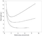
Flow rate: First, let's consider the mobile phase flow rate. One popular way of illustrating the influence of the flow rate on column efficiency is to make a van Deemter or Knox plot, as shown in Figure 1. This is a graph of the plate height, H, versus the mobile phase linear velocity. The plate height is inversely proportional to the plate number (N = L/H, where L is column length), so smaller plate heights mean larger plate numbers, or more efficient columns. The linear velocity is proportional to the flow rate (same diameter columns assumed), and in the case of Figure 1, a linear velocity of 2 mm/s is approximately equal to a flow rate of 1.2 mL/min. Look first at the top plot of Figure 1, for a 5-μm dp column. You can see that there is a minimum in the curve at approximately 1–1.2 mL/min — this means that the column performs best at this flow rate. As the flow rate is increased, the line rises, meaning that the plate number drops and resolution will get worse. So speeding up the run by increasing the flow rate for a 5-μm dp column will result in lower column efficiency. From a practical standpoint with real samples under real conditions, we usually can change the flow rate by a factor of two and not notice a change in resolution, but larger changes in flow can visibly reduce resolution. Of course, pressure increases in direct proportion to an increase in flow rate. If your initial method has excess resolution and you don't mind running at a higher pressure, an increase in the flow rate is the easiest way to shorten the run time.

Figure 1: Influence of particle size on column efficiency for 5-μm (top), 3.5-μm (middle), and 1.8-μm (bottom) particles. 2 mm/s velocity â 1.2 mL/min. See text for details.
Column length: Another way to speed up the method is to use a shorter column. If you started with a 150-mm-long column and have extra resolution, you may be able to move to a 100-mm column. The plate number is proportional to the column length, but according to equation 1, resolution is proportional to the square root of the column length. This means that for the same flow rate, the run time (and plate number) drops by (150 – 100)/150 = 33%, but resolution drops only by 6%. And the shorter column means lower back pressure, so you may be able to increase the flow rate with the shorter column and gain even more time. A change in column length can be a very easy way to reduce the method run time, but if columns <100 mm long or <4.6 mm in diameter are used, be careful to minimize extracolumn volume or much of the theoretical gain may be lost to extracolumn band broadening.
Particle size: There has been a tremendous emphasis recently on the use of sub-2-μm dp columns as a means to obtain faster separations. As the plots of Figure 1 show, the plate height is directly proportional to particle size. This means that a 1.7–1.8 μm particle column will generate approximately three times as many plates as a 5 μm one. This threefold increase in N translates into an increase of 1.7-fold in resolution. A second advantage of smaller particles is that plots as in Figure 1 stay nearly flat as the flow rate is increased. So, whereas a threefold increase in flow rate from 1.2 to 3.6 mL/min (2–6 mm/s) causes an increase in H (and corresponding reduction in N) by 25% for a 5-μm dp column, there is no practical change in column efficiency for the 1.8-μm column with the same change in flow rate. A change from 5-μm particles to sub-2-μm particles gives an increase in N by approximately threefold. This increase can be traded for a shorter column, for example a 50-mm-long column instead of a 150-mm-long column, and give a threefold reduction in the run time, all other factors being held constant. The previous precautions about extracolumn band broadening hold in this situation, too. There is a penalty for smaller particles, however, and this is an increase in backpressure.
The Tradeoffs
As you can see from the above discussion, there are several opportunities to shorten run times by changing the column parameters. However, nothing comes for free, and the same holds true here – there always are tradeoffs with changes in column parameters. Column pressure changes in direct proportion to the flow rate, but for most routine separations, a two-fold change in flow rate will have little noticeable affect on resolution. Most workers run conventional LC systems in the 2000–3000 psi (130–200 bar) range, but most commercial LC systems are capable of operation up to 6000 psi (400 bar). You may have to tighten a few fittings to keep them from leaking, but otherwise, the equipment should function satisfactorily at higher pressures. The change in resolution and pressure can be calculated for a given change in column length, so as long as you stay within the equipment limits you should be fine.
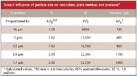
The impact of a change in column parameters becomes a bit more complex when particle size is changed. As is illustrated by the example in Table I, the plate number changes in direct proportion to the particle size, but the resolution changes only with the square root of the particle size change (equation 1). However, the penalty is in pressure — pressure increases with the square of the particle size reduction. So, for example, a twofold reduction in particle size improves resolution by only 40%, whereas the pressure goes up by a factor of four. If we want to take advantage of sub-2-μm particles at higher flow rates, as in Figure 1, it is very easy to exceed the pressure limits of conventional LC equipment. Several manufacturers now offer LC systems capable of pressures > 6000 psi to allow such operating conditions.

Table I: Influence of particle size on resolution, plate number, and pressure*
The practical use of a change in column parameters is shown with the data of Table II. In the first example, use of a 150-mm column packed with 5-μm particles resulted in a method with a retention time, tR, of the last peak of 15 min, a pressure of 2000 psi, and the resolution for the least-resolved peak pair of 2.0. We can try using smaller particles to speed up the separation. A 100-mm-long column packed with 3-μm particles and all other conditions the same will generate the same resolution in 10 min, but at the expense of pressure. The new pressure of 3700 psi is higher than most workers operate their systems, but is well within the system specifications. Use of a 50-mm column packed with 1.7-μm particles will shorten the run time to 5 min, but now we are bumping up against the upper pressure limit for a conventional LC system. It is interesting to note, that if we are willing to operate at this pressure, an increase in the flow rate by a factor of three for the 5-μm column (not shown) will give the same run time, although the resolution will be slightly degraded and much more solvent will be used than with the shorter, 1.7-μm column.

Table II: Examples of column parameter changes
So far we've talked about situations in which the method had excess resolution. What about the case where there isn't quite enough resolution? This is shown in the second example of Table II. The starting separation on the 150-mm, 5-μm column had a resolution of 1.7, but 2.0 was desired. By changing to a 150-mm, 3-μm column, the goal could be achieved, but with pressures just under the operating limits of the system. The 75-mm column packed with 1.7-μm particles also will solve the problem and halve the run time, but it will require an LC system designed for higher pressure use.
Conclusions
We've seen that a change in the column parameters — flow rate, column length, and particle size — can be used to speed up a separation for which excess resolution is present. Column parameter changes also can be used to increase the resolution of a marginal separation. Changes in flow rate will change retention and pressure in proportion to the change. Usually a change in flow rate by a factor of two will not cause a practical loss of column efficiency for most real samples when 5-μm particles are used. Smaller particles are less susceptible to flow rate changes. The results of changes in column length are easy to calculate - N, pressure, and retention time are directly proportional to the changes. Particle size changes can introduce more problems, as illustrated in Table I, because although N changes in proportion to the particle size change and Rs as the square root of the particle size, pressure changes with the square of the particle size change. Thus, particles with diameters < 3 μm may have limited use with conventional LC systems because of pressure limitations of the equipment.
Most of the results discussed here are based on theory. What you obtain with a method separating real samples in your laboratory is unlikely to gain the full benefit of the changes discussed. When any combination of particles < 5 μm, column diameters < 4.6 mm, and column lengths < 150 mm is used, extracolumn band broadening may further compromise the separation. If you are going to be using such conditions, take care to use short lengths of small diameter tubing (for example, 0.005-in. i.d.) to connect the autosampler to the column and column to detector and keep the injection volumes < 20 μL. In general, sub-2-μm particles will require an LC system designed for minimum volume from the injector through the detector, as well as the capability of pressures > 6000 psi.
Changes in column parameters can have a big impact on reducing run times if the initial method has excess resolution. They are not very powerful in trying to rescue a method with sub-standard resolution. For this reason, it often is useful to spend a little extra time during method development to obtain a method with more resolution than is necessary on the standard development column so that you can trade some of that excess resolution for shorter run times.
JohnW. Dolan "LC Troubleshooting" Editor John W. Dolan is Vice-President of BASi Northwest Laboratory of McMinnville, Oregon; a Principal Instructor for LC Resources, Walnut Creek, California; and a member of LCGC's editorial advisory board. Direct correspondence about this column to "LC Troubleshooting," LCGC, Woodbridge Corporate Plaza, 485 Route 1 South, Building F, First Floor, Iselin, NJ 08830, e-mail John.Dolan@Bioanalytical.com
For an ongoing discussion of LC trouble-shooting with John Dolan and other chromatographers, visit the Chromatography Forum discussion group at http://www.chromforum.com.
References
(1) J.W. Dolan, LCGC 25(6), 546–552 (2007).
(2) J.W. Dolan, LCGC 25(7), 632–638 (2007).
(3) J.W. Dolan, LCGC 25(8), 704–709 (2007).
(4) J.W. Dolan, LCGC 25(9), 944–950 (2007).
(5) J.W. Dolan, LCGC 25(10), 1014–1020 (2007).
University of Tasmania Researchers Explore Haloacetic Acid Determiniation in Water with capLC–MS
April 29th 2025Haloacetic acid detection has become important when analyzing drinking and swimming pool water. University of Tasmania researchers have begun applying capillary liquid chromatography as a means of detecting these substances.
Prioritizing Non-Target Screening in LC–HRMS Environmental Sample Analysis
April 28th 2025When analyzing samples using liquid chromatography–high-resolution mass spectrometry, there are various ways the processes can be improved. Researchers created new methods for prioritizing these strategies.

.png&w=3840&q=75)

.png&w=3840&q=75)


.png&w=3840&q=75)


.png&w=3840&q=75)


