Large-Volume Injection LC–MS-MS Methods for Aqueous Samples and Organic Extracts
LCGC Europe
Environmental sample analysis by large-volume injection (LVI) in combination with liquid chromatography–tandem mass spectrometry (LC–MS-MS) is described for polar and nonpolar analytes in both aqueous samples and organic extracts.
Environmental sample analysis by large-volume injection (LVI) in combination with liquid chromatography–tandem mass spectrometry (LC–MS–MS) is described for polar and nonpolar analytes in both aqueous samples and organic extracts. LVI is the direct introduction of large sample volumes (for example, 900–1800 µL) into the LC system for separation and subsequent detection. The practical benefits of LVI include faster sample preparation times, lower detection limits, and minimal waste generation.
Environmental sample analysis by large-volume injection (LVI) in combination with liquid chromatography–tandem mass spectrometry (LC–MS–MS) is the direct introduction of large sample volumes (for example, 900–1800 µL) into an LC system for separation and subsequent detection. The primary advantages of LVI compared to traditional off-line or on-line sample preparation techniques, such as solidâphase extraction (SPE) or liquid–liquid extraction (LLE), include decreased sample preparation, greater analyte mass introduced for detection (that is, increased sensitivity), and less solvent and solid waste. LVI is wellâsuited for the concentration and separation of water-soluble analytes on reversed-phase guard and analytical columns (1), and has also been extended to organic extracts (2). Successful combination of LVI with LC–MS–MS requires an understanding of analyte properties (polarity, stability, and so on) and sample properties (salinity, particulate matter, matrix components, and more) (3,4). The unique elements of several applications are discussed here to highlight the various capabilities and limitations of LVI and are divided between aqueous and organic solvent injections. Finally, a set of loading strategies designed to capture nonionic analytes from large volumes of organic extracts on reversedâphase columns is described and experimental components are listed.
Experimental
An Agilent 1100 high performance liquid chromatography (HPLC) system, upgraded with a 900-µL analytical head and an extended-seat capillary sample loop, was used for all methods described below.
Aqueous Samples: Direct Injection
Past examples of aqueous LVI include the analysis of neurotoxins in drinking water, pharmaceuticals in wastewater, and corrosion inhibitors in surface water (4). Here, two LVI methods are presented with a focus on the important technical features required to inject 1800 µL onto C18 guard and analytical columns. The LVI methods highlighted involve the direct injection of raw wastewater for the determination of illicit drugs (5) and seawater with 25% isopropanol for the determination of the surfactant components in the oil dispersant Corexit (Nalco) (6).
Before injection, raw wastewater is centrifuged to remove particulate matter that can potentially clog columns and other LC components (5). Filtration is a commonly used alternative, but its suitability is method- and analyte-specific because filter membranes can serve as a potential sink or source of analyte contamination (4,7). SPE, however, is not limited by particulate matter and has been used to analyze both the aqueous and particulate bound fraction (8). After centrifugation, the raw wastewater sample is added to an autosampler vial and spiked with isotopically labelled internal standards.
The six-port valve connections in the LC autosampler (Figure 1) are labelled as either mainpass (solid red channel) or bypass mode (dashed blue channel). The mobile phase in mainpass mode flows sequentially through the analytical head, sample loop, needle, extended-seat capillary sample loop, and then onto the columns. Bypass mode directs the flow directly onto the column. Initially, the LC system is operated in bypass mode so that the needle may be inserted in the sample vial and the first 900-µL volume is withdrawn. The needle is returned to its seat and the 900 µL of wastewater is then ejected into a 1400âµL extendedâseat capillary sample loop, which acts as a storage device during the withdrawal of the second 900 µL. Afterwards, the six-port valve is switched to mainpass mode and the cumulative 1800 µL of wastewater sample is chased by the mobile phase out of the sample loops and onto C18 guard and analytical columns. After the sample is out of the sample loops, the sixâport valve switches back to bypass mode. If left in mainpass mode, the gradient would travel through all of the mainpass tubing before reaching the column, requiring that the total run time be extended by several minutes.
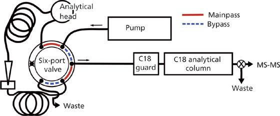
Figure 1: Basic LVI configuration for 1800-μL injections onto a reversed-phase system. The six-port valve and injection assembly was adapted from Agilent autosampler schematics (16).
Both the wastewater sample and initial mobile-phase solvents are aqueous with characteristically low eluotropic strengths on reversed-phase columns, such that methamphetamine and other illicit drugs and biomarkers are focused on the head of the C18 guard column. The guard column protects the analytical column and is preemptively replaced every 50 sample injections. This is ultimately more cost and time effective than using individual SPE cartridges for sample cleanup and analytical column protection. After loading analytes onto the C18 guard and analytical columns, a traditional reversed-phase gradient is used to separate and elute all analytes.
Neither reversed-phase LVI or SPE can selectively remove matrix components that are coeluted with the analytes of interest. With LVI, a postcolumn divert valve can be precisely controlled to divert column effluent containing sample matrix components away from the detector. The control of divert valve timing is achieved with greater precision than the analogous wash steps used in SPE and can send all unfavourable effluent to waste. As will be discussed below, the postcolumn divert valve is of even greater importance with the direct injection of seawater.
An LVI-based method was developed by Place and colleagues (6) using the direct injection of seawater to quantify the surfactant components of Corexit: dioctyl sulphosuccinate (DOSS), Tween 80, Tween 85, and Span 80. Liquid standards of sorbitan monooleate (Span 80; purity: 70.5%), sorbitan monooleate polyethoxylate (Tween 80; purity: 74%), and sorbitan monooleate polyethoxylate (Tween 85; purity: 67%) were obtained from Sigma Aldrich. The direct injection of 1800 µL followed similar steps as described above for wastewater with two crucial adjustments. Open seawater does not require centrifugation and filtration was shown to remove the analytes of interest from solution. In addition, the Corexit surfactants undergo hydrophobic exclusion from aqueous solutions and exhibit significant loss (>50%) to polypropylene or glass container walls within 8 h of sampling at ambient temperature. To prevent analyte loss before analysis, seawater is diluted with isopropanol at the time of collection to give a final composition of 1:3 isopropanol–seawater. Injections of 1800 µL of the isopropanol-stabilized matrix resulted in wellâresolved peaks for anionic and nonionic surfactant classes. At higher additions of isopropanol, there is no improvement of analyte stability in aqueous samples and peak shape begins to suffer.
Direct injection of seawater into the LC–MS–MS system is possible without damaging the mass spectrometer source by using the divert valve to direct the nonvolatile salts contained in seawater to waste. The 1800-µL injection volume (3.6 min loading at 0.5 mL/min) is followed by a 5.9-min “wash” under the primary mobile-phase conditions (5% acetonitrile and 0.5 mM ammonium acetate in water). This wash is diverted to waste and is sufficient to flush the nonvolatile salts from the column and away from the mass spectrometer before elution of the analytes of interest. The time (5.9 min) used to wash the salts from the seawater from the columns was evaluated by testing effluent fractions collected at 30-s intervals with the addition of 100 µL of 1 M silver nitrate–0.6 M nitric acid. The presence of chloride in the collected effluent was determined by the formation of a white silver chloride precipitate, visible in aqueous solutions containing more than 0.1% seawater. No silver chloride was observed in the effluent 7.5 min after injection and a precautionary period of 2 min was added to extend the loading and wash period to 9.5 min. For this application, guard columns are replaced approximately every 100 injections and the analytical column was replaced after approximately 1500 injections. Analysis over two years and more than 5000 injections did not lead to salt accumulation or corrosion in the LC–MS–MS system.
Organic Extracts: Orthogonal Chromatography
Sample treatment to create organic extracts is desirable if analytes are unstable in aqueous solution, because of hydrolysis or hydrophobic exclusion, or if the sample matrices (for example, landfill leachate) are sufficiently complex that significant sample cleanup is required before injection. In addition, some analytes do not focus well on reversedâphase columns, even under high aqueous conditions, and require a different retention mechanism. For example, per- and polyfluorinated alkyl substances (PFAS) present in landfill leachate are commonly concentrated by SPE before injection (8) because of leachate matrix complexity. Direct aqueous injection for PFAS analysis is additionally disadvantageous because polar PFAS are not retained well on reversed-phase columns and the more hydrophobic PFAS are lost from aqueous matrices onto autosampler vials and to the air–water interface. The two new strategies discussed here for the LVI of PFAS in an organic solvent extract from leachate include orthogonal chromatography (9) and on-line extract dilution.
In-line orthogonal chromatography was developed for PFAS in ethyl acetate–trifluoroethanol extracts of landfill leachates (9). The orthogonal columns system consisted of two zirconiumâmodified diol (Zr-diol) guard columns (6 µm, 150 Å, 12.5 mm × 4.6 mm, Agilent) placed in-line with a Zorbax Eclipse Plus C18 analytical column (3.5 µm, 95 Å, 75 mm × 4.6 mm, Agilent) (Figure 2). The system proved capable of capturing 70 anionic PFAS from 900âµL injections of the 1200-µL ethyl acetate–trifluoroethanol extract, which is 75% of the extract volume generated.
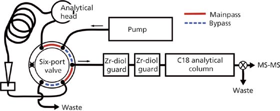
Figure 2: Schematic of configuration for PFAS analysis in leachate extracts.
The PFAS are captured by the Zr-diol columns through interactions between the anionic PFAS and the zirconium d-orbitals during the 900-µL injection of the ethyl acetate–trifluoroethanol extract. The trapped PFAS are then eluted from the Zr-diol guard columns by a mobile phase containing 50% methanol and 5 mM ammonium acetate that then refocuses the majority of analytes on the C18 analytical column. PFAS are then separated by a traditional reversedâphase gradient with an increasing percentage of organic solvent (Figure 3). Without LVI, additional sample preparation steps like solvent transfer and blowâdown are necessary to introduce sufficient analyte mass in the small injection volumes typically used (such as 10–20 µL). Moreover, an injection of 10–20 µL of an extract concentrated into about 100 µL is, at most, 20% of the total extract volume generated. Comparatively, LVI capitalizes on the time, effort, and labour costs expended during the creation of organic extracts by analyzing a greater percentage, while also eliminating additional steps that increase the possibility of analyte loss.
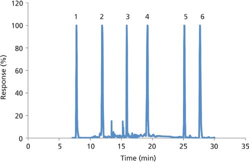
Figure 3: Typical leachate chromatogram for select PFAS using the Zr-diol guard column configuration. Peaks: 1 = PFBA, 2 = PFHxS, 3 = PFOS, 4 = MeFBSAA, 5 = 6:2 DiPAP, 6 = PFHxDA.
Organic Extracts: Dilution
Orthogonal chromatography (as described above) is not capable of capturing nonionic PFAS from a large volume of organic extract. Dilution of organic extracts with water is one approach to perform LVI for the analysis of nonionics in organic extracts (for example, pesticides in vegetable [10] or soil extracts [11]). The traditional use of small-volume injections with organic solvent extracts of high eluotropic strength achieve focusing of analytes on reversed-phase columns because of dilution of the small organic extract volume with the larger volume of initial aqueous mobile phase. In the case of PFAS in landfill leachates, an eightfold dilution with water would be needed to retain the most water-soluble, nonionic PFAS on C18 columns (for example, MeFBSA). For comparable levels of sensitivity using off-line dilution, the 900-µL extract, injected previously, would become at least 7.1 mL and require multiple large autosampler vials, larger extended sample loops, and a longer injection programme. However, as previously mentioned, many PFAS can partition out of the bulk solution under high aqueous conditions. Therefore, on-line dilution strategies are explored here.
The objective of the following dilution-based LVI method is to use the ethyl acetate–trifluoroethanol leachate extracts and the orthogonal Zr-diol–C18 column system for the analysis of nonionic PFAS. Thus, the first alternative to offâline dilution was to inject 900 µL in small volume “packets” segmented by defined volumes (determined by flow rate and time) of the initial aqueous mobile phase. To minimize the overhead time required by the autosampler transport assembly to inject multiple small volumes, one 900-µL volume was drawn up into the sample loop and loaded onto the column in small packets by switching back and forth between mainpass and bypass mode (Figure 2). The volume of packets is determined by the flow rate and time spent in mainpass mode. The flow rate while loading packets onto the Zr-diol guard columns and C18 analytical column was 2 mL/min and the times spent in mainpass and bypass mode were programmed as 0.01 and 0.3 min, respectively (Figure 4). Mainpass and bypass were switched back and forth 18 times over the first 7.5 min where the sixâport valve was left in mainpass mode for 1 min the last time. At 8.3 min the gradient was started in bypass mode and the flow rate was decreased to 0.5 mL/min.
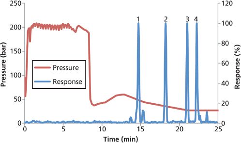
Figure 4: Pressure isotherm and chromatogram for mainpass and bypass packet injections. Landfill leachate peaks for ionic PFAS: 1 = PFBA, 4 = PFOcDA. Nonionic PFAS peaks: 2 = MeFBSA, 3 = EtFOSA.
The solvents in the mainpass assembly are pressurized when the six-port valve is in mainpass mode. But when in bypass mode, small volumes are lost to the waste line on the six-port valve as the mainpass assembly solvents depressurize and expand. Consequently, the six-port valve leading to waste (Figure 2) was plugged with a blanking nut to avoid losing small volumes of sample while switching between mainpass and bypass mode. Because the waste line was plugged, the 900 µL of mainpass solvent normally ejected to waste in preparation for drawing up sample were instead programmed to eject into an empty sample vial.
When samples are loaded using this on-line, packetâdilution configuration, both ionic and nonionic PFAS are captured and separated from landfill extracts (Figure 4). The most water-soluble ionic (PFBA) and nonionic (MeFBSA) PFAS are successfully retained after 18 packet injections of leachate extract.
The LC pressure isotherm (Figure 4) is an important tool to aid method development. Pure and mixed solvents have different viscosities and therefore exert different corresponding back pressures that can be used to track gradient and sample delivery. The sawtooth pressure profile during the first 7.5 min is evidence of extract solvent packets mixing with the aqueous mobile phase in the Zr-diol guard columns. While programmed as 0.01 and 0.3 min, the actual times spent in mainpass and bypass mode were calculated using the average frequency of packet mixing seen in the pressure isotherm and were closer to 0.028 and 0.35 min, respectively. So at 2 mL/min the average packet was 56 µL with 700 µL of aqueous mobile phase on either side. The volume of mobile phase on both sides of the organic packets effectively dilutes the extract solvent inside the Zr-diol guard columns, thus reducing the eluotropic strength of the sample solvent so that focusing of the nonionic PFAS occurs on the C18 analytical column. The Zr-diol guard columns were more effective mixing chambers than other guard columns (such as amino propyl, C18) that required smaller packet volumes to focus nonionic PFAS on the head of the C18 analytical column. After loading nonionic PFAS the analytes were eluted from the Zr-diol guard columns and C18 analytical column separately; the anionic PFAS were focused on the Zr-diol columns and nonionic PFAS were focused on the C18 column.
The second alternative strategy is to trap nonionic PFAS from an organic extract on reversed-phase columns using a variation of at-column dilution that divides the flow from a single pump. At-column dilution typically uses two pumps that either pushes the sample at a slow flow rate to the tee junction or pumps a weak solvent at a high flow rate that dilutes the sample when the two flows combine at the tee (12). The amount of sample dilution is a function of the two flow rates. At-column dilution has been applied to load larger sample volumes onto columns during preparative LC (13) or analytical LC (for example, pesticides in river water using on-line SPE with LC–MS–MS) (14). The advantage of dividedâflow at-column dilution is that a second pump does not need to be purchased and at-column dilution is achieved using only two tee junctions and tubing of different internal diameters (Figure 5).
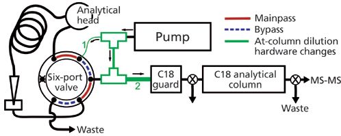
Figure 5: Divided-flow at-column dilution schematic. The tubing internal diameters for tubing 1 and 2 were changed from 0.175 mm to 0.125 and 0.76 mm, respectively.
Chromatographic separation was accomplished using a Zorbax Eclipse Plus C18 guard column (12.5 mm × 4.6 mm, 5-µm Agilent) and a Zorbax Eclipse Plus C18 analytical column (75 mm × 4.6 mm, 3.5-µm Agilent). The internal diameter of the tubing between the tee and the autosampler six-port valve (Figure 5) was decreased from 0.175 to 0.125 mm. The internal diameter of the tubing connecting the two tees was 0.175 mm and the internal diameter of the 3-cm length of tubing on the outflow of the second tee and before the C18 guard column was large (0.76 mm) to ensure complete mixing of the two recombined flowpaths. Mobileâphase A consisted of 3% methanol in deionized water and mobile phase B consisted of 100% methanol and 10 mM ammonium acetate. The initial aqueous mobile phase flow rate was 3 mL/min for 3.5 min, during which time the 900âµL leachate extract was loaded onto the C18 guard column. The C18 guard column effluent was sent to waste for the first 3.5 min to keep the pressure low during the high flow rate. After 3.5 min the flow rate dropped to 0.5 mL/min and the guard column effluent was directed onto the analytical column. The gradient was then increased to 100% over the next 10 min and held for 5 min. PFAS were detected using a Quattro Premier XE MS–MS system (Waters Corporation), operated in multireaction monitoring mode.
Adequate dilution of the organic extract before the C18 guard column is evidenced by nonionic peak retention and symmetry (Figure 6). More polar PFAS (such as PFBA) were not retained using only a C18 guard column. To capture anionic PFAS additional guard columns with orthogonal retention mechanisms (for example, Zr-diol) can be added before or after the C18 guard column with minimal increases to the back pressure.
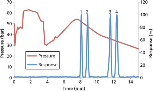
Figure 6: Divided-flow at-column dilution pressure isotherm and chromatogram. Peaks 1 = PFHxS, 2 = MeFBSA, 3 = EtFOSA, 4 = PFOcDA.
While in mainpass mode the flow was divided at the first tee following the pump (Figure 5), with less mobile phase being directed through the sample loop. The reduced flow of mobile phase in the sample loop slowly moved the sample volume to where it combined with the rest of the flow at the second tee. The pressure isotherm (Figure 6) increased 1 min after switching to mainpass mode when the diluted 900-µL organic solvent extract first reached the guard column. After 3.5 min the entire sample had passed through the guard column and the C18 guard column was once again filled with the aqueous mobile phase. For 900 µL to pass through the guard column in under 2.5 min the flow rate through the autosampler was at least 0.36 mL/min, which corresponds to a 8.3-fold dilution when combined at the second tee with the rest of the 3 mL/min. Reducing the internal diameter of the tubing leading to the six-port valve from the first tee from 0.175 to 0.125 mm effectively reduced the percent flow to the six-port valve from 20% to 12% to achieve the eightfold dilution necessary for nonionic PFAS retention.
The incidental introduction of foreign matter can adversely change the internal diameter and by extension the percent flow to the six-port valve will also change (15). Should the internal diameter change significantly, samples may not be sufficiently diluted or may take longer to load onto the column. The risk of foreign matter introduction can be reduced by centrifuging or filtering the samples and mobile phases. Any change of the flow division at the first tee will be evident in the pressure isotherm profile, and clogged tubing can be cleared with extended flushing (15) or easily replaced; the divided-flow at-column dilution tubing used is relatively short (<5 cm) and therefore inexpensive. Overall, divided-flow at-column dilution has a simple, more universal configuration compared to “packet injections,” and it exerts lower back pressures, is faster, and can be used to inject more than 900 µL by using the extending capillary (Figure 1) used in the wastewater and seawater methods described above.
Conclusion
LVI combined with LC–MS–MS offers several advantages over traditional small-volume injection and off-line sample cleanup techniques without diminished method performance. Direct injection LVI often requires little to no sample preparation and reduces solid and solvent waste generation associated with traditional off-line sample preparation. The injection of large sample volumes is analogous to the concentration step of SPE and increases the sensitivity of a given analysis by introducing more mass of the analytes of interest to the detector. Matrix components can be separated from the analytes of interest with greater specificity using LVI because of the control afforded by gradient elution and waste divert valves. Centrifugation or filtration is necessary before the direct injection of aqueous samples with suspended particulate matter, whereas some SPE-based methods simultaneously analyze the dissolved and particulate phases.
When matrix complexity or analyte stability require the generation of an organic extract, LVI capitalizes on the time, effort, and labour costs expended by injecting a larger percentage of the total extract volume. LVI of organic extracts also shortens sample preparation without a loss in sensitivity by eliminating additional steps associated with small volume injections (such as solvent evaporation) and the corresponding opportunities for analyte loss. Direct injection of organic extracts onto orthogonal columns was sensitive and robust, but was limited to ionic analytes. On-line dilution of organic extracts enables both ionic and nonionic analyte retention on reversedâphase columns and is preferable to off-line dilution for analytes unstable in aqueous solution. Divided-flow at-column dilution required only one pump, tee junctions, and tubing and efficiently focused anionic and nonionic analytes onto a reversed-phased system.
References
(1) T. Reemtsma, L. Alder, and U. Banasiak, J. Chromatogr. A1271, 95–104 (2013).
(2) W.J. Backe, T.C. Day, and J.A. Field, Environ. Sci. Technol.47, 5226–5234 (2013).
(3) W.J. Backe and J.A. Field, Environ. Sci. Technol.46, 6750–6758 (2012).
(4) F. Busetti, W.J. Backe, N. Bendixen, U. Maier, B. Place, W. Giger, and J.A. Field, Anal. Bioanal. Chem.402, 175–186 (2012).
(5) A.C. Chiaia, C. Banta-Green, and J. Field, Environ. Sci. Technol.42, 8841–8848 (2008).
(6) B.J. Place, M.J. Perkins, E. Sinclair, A.L. Barsamian, P.R. Blakemore, and J.A. Field, Deep Sea Research II (http://dx.doi.org/10.1016/j.dsr2.2014.01.015i) (2014).
(7) J.W. Martin, K. Kannan, U. Berger, P.D. Voogt, J. Field, J. Franklin, J.P. Giesy, T. Harner, D.C.G. Muir, B. Scott, M. Kaiser, U. Järnberg, K.C. Jones, S.A. Mabury, H. Schroeder, M. Simcik, C. Sottani, B.V. Bavel, A. Kärrman, G. Lindström, and S.V. Leeuwen, Environ. Sci. Technol.38, 248A–255A (2004).
(8) J.P. Benskin, M.G. Ikonomou, M.B. Woudneh, and J.R. Cosgrove, J. Chromatogr. A1247, 165–170 (2012).
(9) B.M. Allred, J.R. Lang, M.A. Barlaz, and J.A. Field, J. Chromatogr.A1359, 202–211 (2014).
(10) A.C. Hogenboom, M.P. Hofman, S.J. Kok, W.M.A. Niessen, and U.A.T. Brinkman, J. Chromatogr. A892, 379–390 (2000).
(11) I. Rybar, R. Gora, and M. Hutta, J. Sep. Sci. 30, 3164–3173 (2007).
(12) "At-Column Dilution Application Notes," Waters Corp., Milford, Massachusetts, 2003, pp. 1–22.
(13) K.F. Blom, J. Comb. Chem.4, 295–301 (2002).
(14) H. Sasaki, J. Yonekubo, and K. Hayakawa, Anal. Sci.22, 835–840 (2006).
(15) J.W. Dolan, LCGC North Am.19, 478–482 (2001).
(16) Agilent Technologies, Agilent 1100 Series Standard Micro and Preparative Autosamplers, Agilent Technologies, Germany, 2001, pp. 205–206.
B. McKay Allred is with the Department of Chemistry and Matthew J. Perkins and Jennifer A. Field are with the Department of Environmental and Molecular Toxicology, all at Oregon State University, in Corvallis, Oregon. Direct correspondence to: jennifer.field@oregonstate.edu

Understanding FDA Recommendations for N-Nitrosamine Impurity Levels
April 17th 2025We spoke with Josh Hoerner, general manager of Purisys, which specializes in a small volume custom synthesis and specialized controlled substance manufacturing, to gain his perspective on FDA’s recommendations for acceptable intake limits for N-nitrosamine impurities.


