Improved Performance of UHPLC–MS Hyphenated Systems
An ultrahigh-pressure liquid chromatography–mass spectrometry (UHPLC–MS) research prototype instrument was built to improve the resolution power and the usability of conventional LC–MS hyphenated instruments for routine analyses in pharmaceutical applications. The improved characteristics of this UHPLC–MS system include: 1) the dramatic reduction of post-column sample dispersion; 2) the adoption of vacuum jacketed columns (VJC) for the reduction of undesirable radial temperature gradients across the column diameter; and 3) the presence of a column outlet end nut heater to refocus the distorted peaks prior to analyte ionization. The benefits of each of these added features are analyzed with a rigorous approach from a peak broadening perspective. A 2x improvement in peak capacities recorded with this prototype UHPLC–MS system compared to a standard system (Acquity UHPLC I-class/Xevo TQ-S) is illustrated for the gradient separation of seven small pharmaceutical compounds using a 2.1 mm x 100 mm column packed with sub-2-μm core-shell particles (1.6 μm Acquity UHPLC Cortecs C18 column).
Hyphenated liquid chromatography–mass spectrometry (LC–MS) systems have become the most widespread and routine separation detection techniques in metabolomics, proteomics, and lipidomics, as well as in the pharmaceutical and agricultural industries (1–10). The move from LC–MS to ultrahigh-pressure liquid chromatography (UHPLC)–MS during the 2000s after adopting small volume columns (2.1 mm i.d., 5–10 cm long) packed with very fine particles (sub-2-μm) has revealed the resolution limit of standard LC–UV and LC–MS hyphenated instruments (11–17). In gradient elution, the observed loss of peak resolution relative to the expected performance of the column alone is essentially because of the large post-column sample dispersion (18). The transport of the analyte from the LC column outlet to the electrospray ionization (ESI) source usually occurs via several lengthy connecting tubes and a divert (infusion) valve, which together generates a significant amount of sample dispersion relative to that caused by the column itself. Peak capacity is then severely reduced unless a solution is found to eliminate or at least minimize post-column dispersion (13,16,17).
The practical problem encountered in conventional UHPLC–MS instruments is that the position of the column oven in the LC instrument stack is remote from the ESI source of the mass spectrometer. Therefore, the UHPLC-to-MS connecting tube dimensions are unsuitable for UHPLC columns to perform at their best. For instance, the Acquity UHPLC I-class/Xevo TQ-S hyphenated system is equipped with a 60 cm x 100 μm tube connecting the column outlet to a divert/infusion valve and a 75 cm x 125 μm tube connecting this valve to the ESI source: overall, they account for a total post-column dispersion variance close to 13 μL2 (small molecules, 1 mL/min). In contrast, the dispersion variance of a 2.1 mm x 100 mm column packed with 1.6 μm core-shell particles is only of the order of 3 μL2 in gradient elution for a retention factor approximately 1 at elution. In practice, it amounts to observing a peak capacity that is approximately half that theoretically expected from new generations of UHPLC columns.
This work proposes a solution by redesigning the interface between the UHPLC instrument and the mass spectrometer. In the first part of this article, a research prototype UHPLC–MS instrument is built. Its specific features are described to illustrate the main problem of excessive post column dispersion while maintaining the integrity of the column performance. In the second part, each modification of the conventional UHPLC–MS instrument is justified from a sound and quantitative approach. Finally, it is illustrated from a concrete pharmaceutical separation problem how much gain in peak resolution and sensitivity the users can benefit from the prototype system relative to conventional UHPLC–MS instruments.
Materials and Methods
LC–MS Gradient Experiments
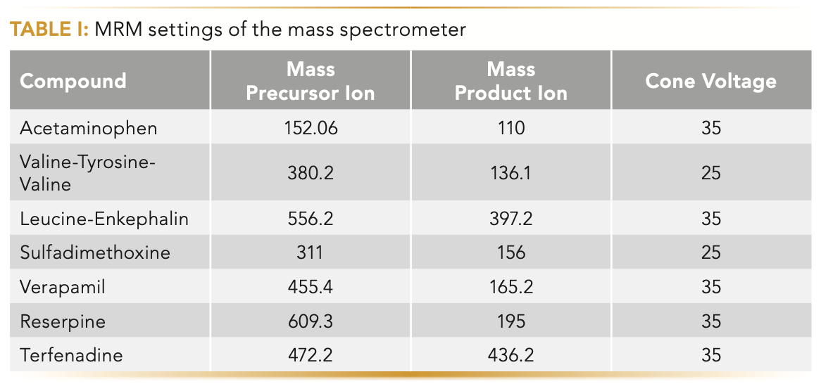
Seven pharmaceutical compounds (acetominophen 10 μg/L, valine-tyrosine-valine 2.5 μg/L, leucine-enkephalin 2.5 μg/L, sulfadimethoxine 1 μg/L, verapamil 0.6 μg/L, reserpine 1.9 μg/L, and terfenadine 0.6 μg/L) were prepared in a mixture of acetonitrile and water (75/25, v/v) and injected under a gradient condition in a 2.1 mm x 100 mm Acquity UHPLC Cortecs C18 1.6 μm column (Waters). The LC system is the Acquity UHPLC I-class equipped with a binary solvent manager and a fixed loop sample manager (Waters). The vacuum jacketed columns were outfitted in house with custom vacuum sleeves. The injection volume, the flow rate, and the inlet eluent temperature were set at 0.3 μL, 0.6 mL/min, and 50 °C, respectively. Two solvent bottles (A and B) were prepared: solvent bottle A contained 0.1% (v/v) formic acid in water, and solvent bottle B contained 0.1% (v/v) formic acid in acetonitrile. The volume fraction of B was programmed to increase linearly from 2% to 98% over 3 min. The analyte detection was performed under the multireaction monitoring (MRM) mode of the Xevo TQ-S mass spectrometer (Waters). The dwell time, the capillary voltage, the source temperature, the desolvation temperature, the desolvation flow rate, and the cone flow rate were fixed at 3 ms, 3.0 kV, 120 °C, 600 °C, 1000 L/hr, and 150 L/hr, respectively, for all compounds. All the other MS detector details specific to the analyte (cone voltage, masses of precursor, and product ions) are given in Table I.
LC–UV Isocratic Experiments
In this series of isocratic experiments, the same column and UHPLC system as those described above were used, except the column outlet was connected to the optical TUV detector (250 nL volume, 254 nm wavelength, 40 Hz sampling rate) using a 15 cm x 75 μm connecting tube. The sample mixture is a solution of acenaphthene (0.2 g/L) and octanophenone (0.1 g/L) prepared in a 25:75 (v/v) mixture of water:acetonitrile, which was also the solvent composition used as the mobile phase. The injection volume, the flow rate, and the inlet eluent temperature were set at 0.5 μL, 0.6 mL/min, and 50 °C, respectively.
Simulation of the Temperature Profiles
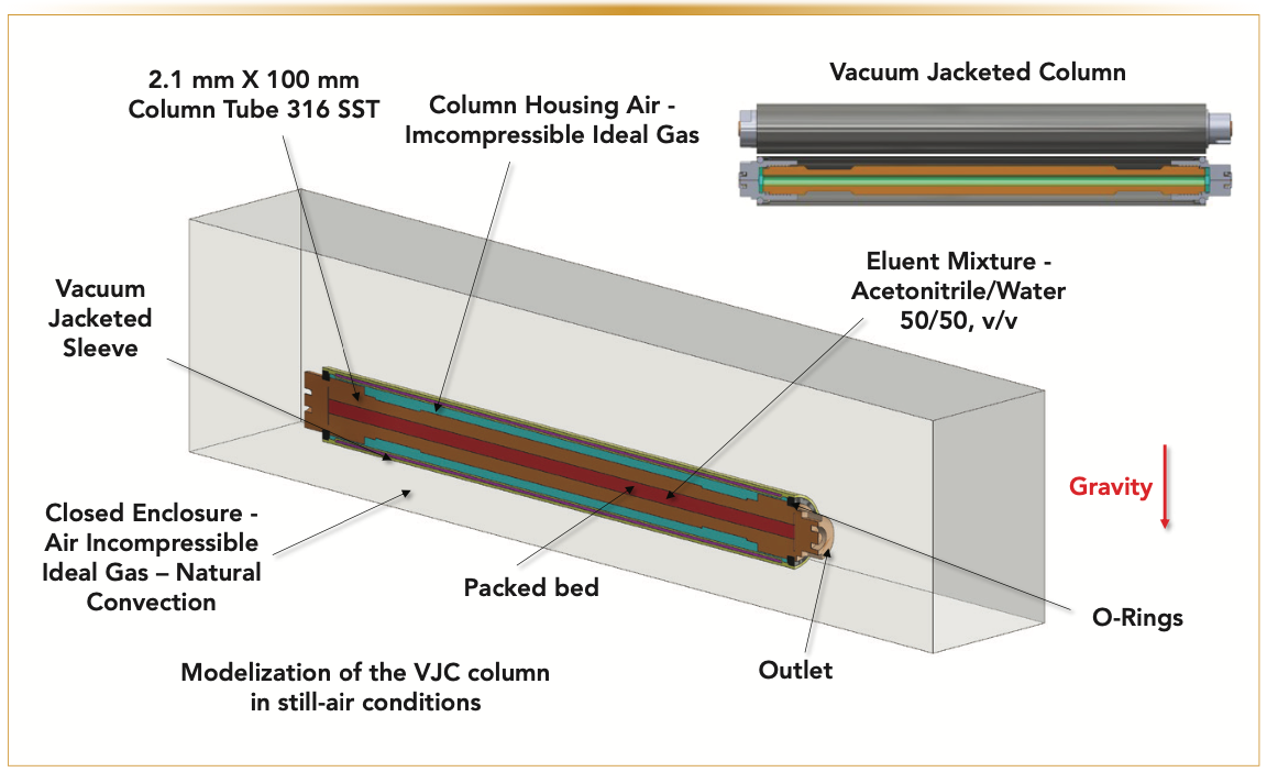
In this work, the radial temperature profiles (from r = 0 to r = 1.05 mm) expected across the packed bed diameter at the column outlet z = 10 cm) were simulated under a steady-state temperature regime by considering the most realistic design and structure of the vacuum jacketed column (VJC) as shown in Figure 2. All the modeling and post-analysis were done using Ansys Fluent 2020 R2 software.
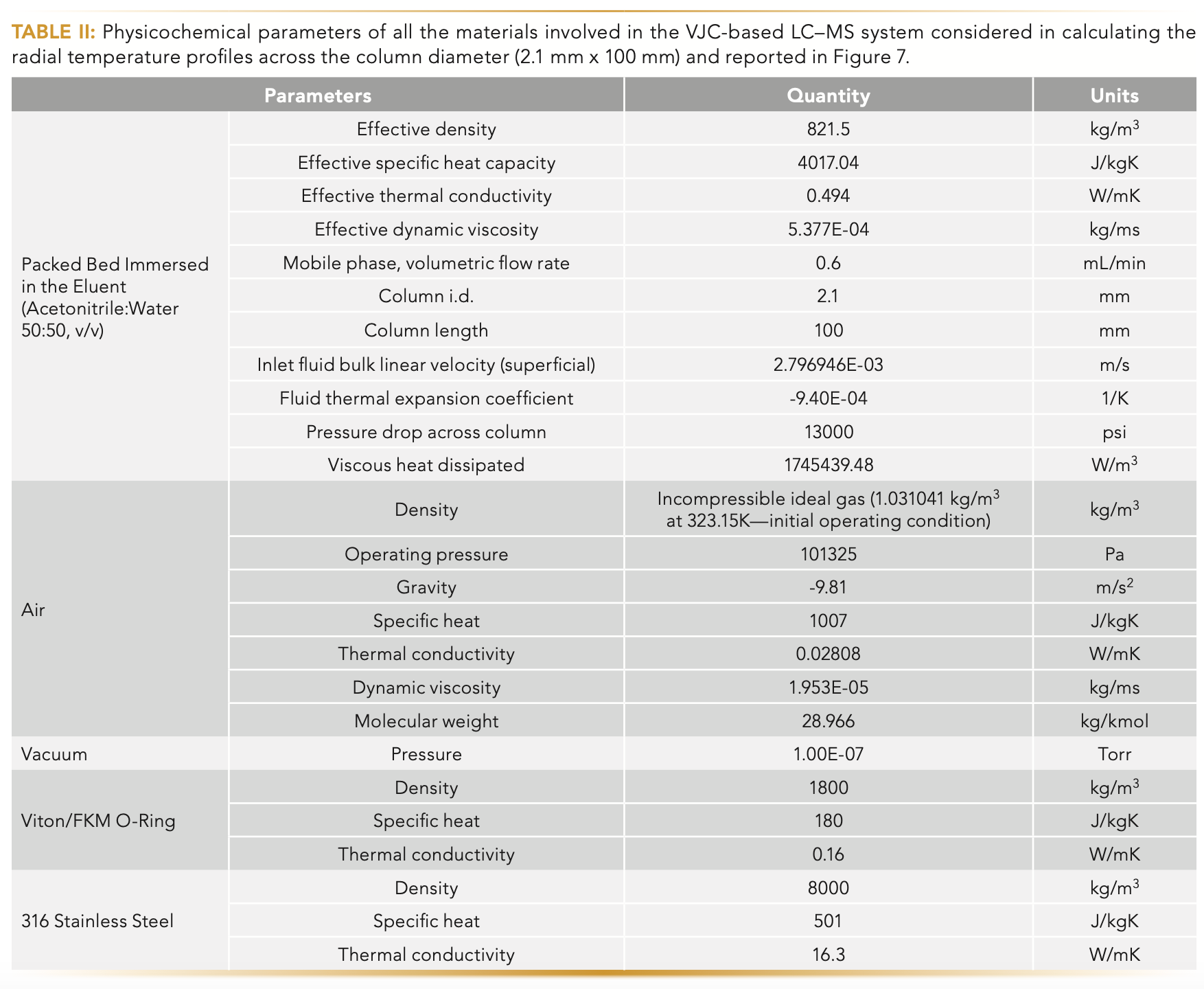
Briefly, a minimum element size of 75 μm was selected for the packed bed zone and features under 5 μm were not featured. A total of 6,940,547 nodes and 14,984,108 elements were generated. The model is based on a pressure-based steady-state solver with double precision and considers gravity to resolve natural convection. A coupled solver was used for solving pressure-velocity coupling of the Navier-Stokes momentum, Navier-Stokes energy, and the continuity equation. Based on its bulk superficial velocity and Reynold’s number, a laminar viscous model with viscous heating was used for the eluent mixture (acetonitrile:water 50/50, v/v). The thermal profile inside the packed bed zone was modeled assuming an energy source term for the eluent mixture without modeling the actual details of the macroporous zone. The viscous heat that was generated was calculated from the total pressure drop, the volumetric flow rate, the fluid inlet temperature, and the thermal expansion coefficient of the eluent. The surrounding air was modeled as an incompressible ideal gas. The inlet boundary condition is set by the inlet superficial linear velocity of the eluent at a fixed temperature of 50 °C. The post-column heater was set at a uniform and constant temperature boundary condition, which was increased from 60 °C to 75 °C in subsequent simulations. Table II lists all the necessary physicochemical parameters assumed in the calculation.
Results and Discussion
Overall Description of the Novel Research Prototype UHPLC–MS System
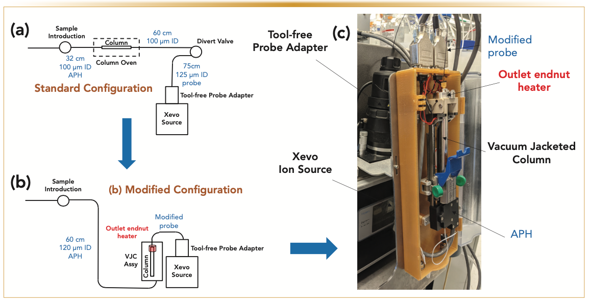
The key motivation underlying the proposed design of the UHPLC–MS research prototype system is to eliminate most of the post-column sample dispersion occurring from the column outlet to the divert (infusion) valve and the ESI source. Figure 1 shows schematics of the standard and modified systems (left) and photography of the research prototype system (right). The chromatographic column (2.1 mm x 100 mm, 1.6 μm Cortecs C18 superficially porous particles) was placed on a prototype column holder fixed directly onto the atmospheric pressure ionization (API) source enclosure. The post-column tubing assembly of the modified UHPLC–MS system was optimized to minimize the post-column dispersion. Overall, the post-column dispersion variance is reduced from approximately 13 μL2 (for a 60 cm x 100 μm tube + a divert (infusion) valve + a 75 cm x 125 μm tube) to approximately 0.3 μL2 only. The gain in performance is discussed quantitatively in the next section.
FIGURE 1: Schematics of the (a) standard and (b) modified configurations of the LC–MS systems and (c) photography of the modified system. The key modifications of the stan- dard system consist of eliminating the column oven, drastically reducing post-column sample dispersion, wrapping the column in a vacuum jacket, and placing an end nut heater at the column outlet.
The injection valve of the I-class Acquity UHPLC system is now connected to the column inlet via a 60 cm x 120 μm i.d. Peek tube in addition to an active eluent preheater (APH). The relatively large precolumn dispersion of the APH (~6 μL2) is not a severe issue in gradient elution because of the sample focusing at the column head. The eluent temperature at the column inlet can still be controlled over a wide range from room temperature to 90 °C. The anticipated problem of placing the column outside the standard air oven compartment (the oven temperature is usually equal to the inlet eluent temperature) is the cooling of the column wall because of heat exchange with the surrounding air at room temperature. Consequently, the lack of control of the column wall temperature and the loss of column performance because of the column-to-laboratory temperature mismatch requires a solution to avoid the formation of undesirable radial temperature gradients (19–22). Therefore, the column was wrapped in a vacuum jacket (see Figure 2), described in great detail in two previous special issues of LCGC North America (23,24). The benefit of the VJC is that the heat delivered at the column inlet (25 °C < Tinlet < 90 °C) can no longer be dissipated by heat exchange between the column wall (hot, T ≥ 25 °C) and the surrounding air (cool, room temperature), so the overall column temperature can be controlled.
FIGURE 2: Three-dimensional (3D) model of a VJC column left in still-air condition. This model simulates the steady-state temperature profiles along and across the entire column volume, including the packed bed volume (2.1 mm x 100 mm). The numerical simulation has accounted for all geometrical details of the different actual elements.
However, small residual heat leaks are detected at the column ends and negatively affect the column performance (24). Therefore, an outlet end nut heater is placed at the outlet of the column to reverse the heat flow direction from outside to inside the column. The anticipated effect is to refocus the tailing peaks and recover the full column performance. The benefit of the outlet end nut heater maximizing column performance will be demonstrated and explained in detail in the next section (using an infrared [IR] camera and simulation of the temperature profiles across the packed bed).
The Rationale Behind the UHPLC–MS System Modifications
In this section, it is justified from scientific arguments (analysis of the peak volume variance, IR surface temperature profiles, simulation of the column temperature profiles, and explanation of the observed change in peak asymmetry) why the configuration of standard LC–MS systems had to be modified. It is explained how the gradient performance of current LC–MS systems is improved every step of the way by 1) reducing the post-column sample dispersion; 2) wrapping the column in a vacuum jacket; and 3) delivering heat locally to the column outlet end fitting using an end nut heater.
Post-Column Dispersion
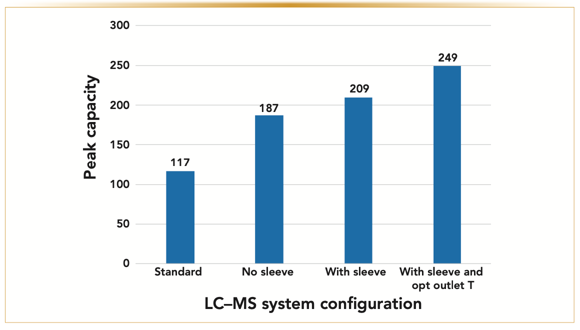
Figure 3 justifies why the post-column modifications are critical in LC–MS when operating a narrow-bore 2.1 mm i.d. x 100 mm long column packed with 1.6 μm Cortecs-C18 core-shell particles. Each solid-colored curve represents all the possible combinations of post-column dispersion (y-axis) and retention factor, kelution, at elution (x-axis), leading to the same apparent gradient peak capacity equal to a fraction, p (0.32 < p < 0.98), of the maximum theoretical gradient peak capacity expected when the post-column dispersion is strictly equal to zero. Assuming that the gradient compression factor is close to 1 (that is, small molecules) and the retention factor at elution is 1, then a standard UHPLC–MS system with a post-column sample dispersion equal to 13 μL2 would lead to a fraction p ~0.44. Therefore, the gradient peak capacity observed is no more than 44% of the maximum peak capacity. Reducing the post-column sample dispersion from 13 μL2 down to only 0.3 μL2 (see the vertical blue arrow) increases p from 0.44 to 0.95: the observed peak capacity is now equal to 95% of the maximum peak capacity or a relative increase of 116% compared to that observed for the standard UHPLC–MS system. Nevertheless, in contrast, Figure 4 reveals experimentally that the peak capacity increases from 117 (reference LC–MS system configuration: “Standard”) to only 187 (60%, modified “No sleeve” configuration) with reduced post-column sample dispersion. This less-than-expected performance gain is explained by the fact that the eluent temperature cannot be maintained at Tinlet = 50 °C along the entire column length because of heat losses towards the external environment. This problem calls for additional modification of the instrument.
FIGURE 3: Plots (solid-colored thick lines) of the fraction p (from p = 32 to 44, 55, 76, 91, 95, and to 98%) of the maximum peak capacity theoretically expected as a function of the post-column dispersion (y-axis) and retention factor kelution at elution (x-axis). The 2.1 mm x 100 mm column is packed with 1.6 μm Cortecs-C18 particles (Nintrinsic = 40,000). The two horizontal dashed lines represent the post-column dispersion variance of the standard (13 μL2) and modified (0.3 μL2) LC–MS systems. The vertical blue arrow indicates the expected and theoretical gain, 95/44 = +116%, of the peak capacity after modifying the standard LC–MS system shown in Figure 1.
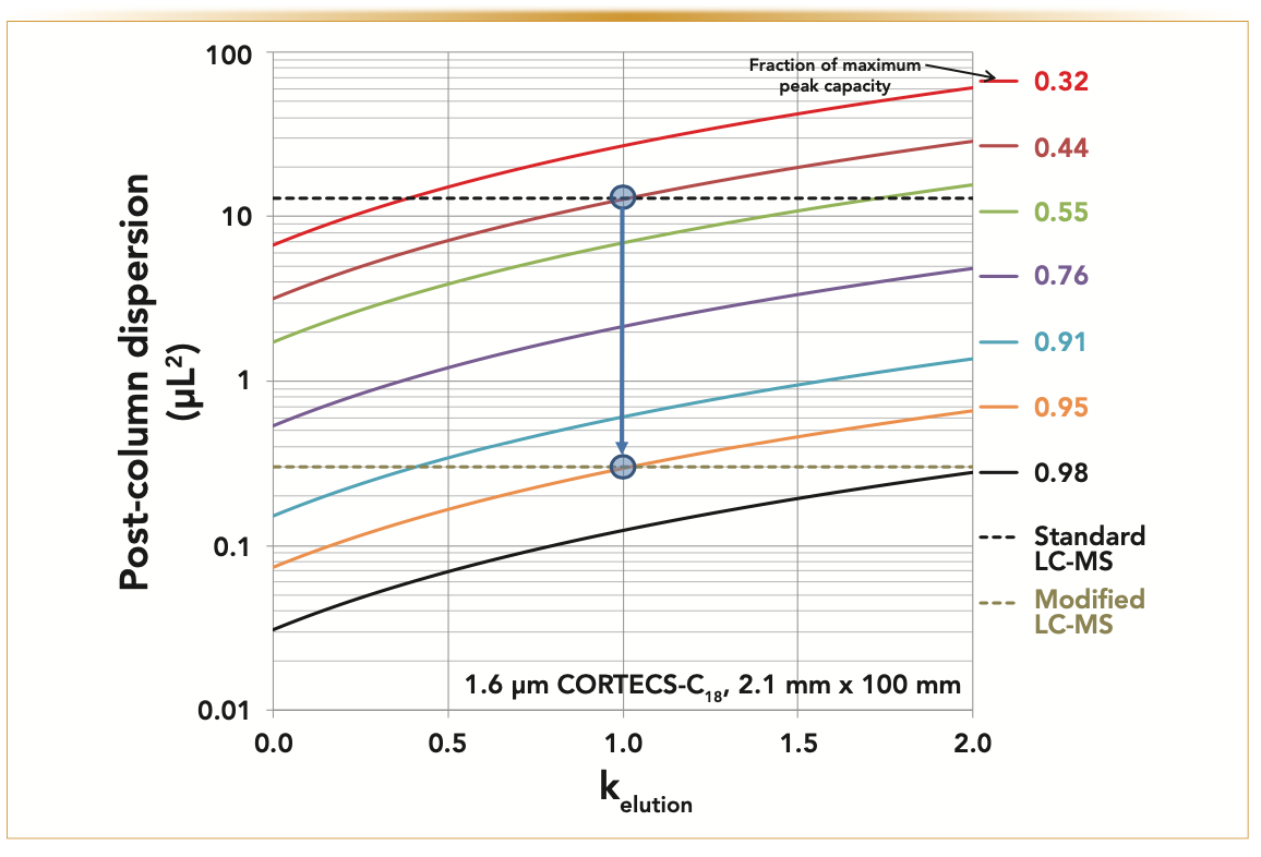
FIGURE 4: Showing the VJC configuration performance comparison (Tinlet = 50 °C). Variation of the experimental gradient peak capacity as a function of the four system configurations investigated in this work: 1) “Standard” → Classical LC–MS system; 2) “No sleeve” → Modified LC–MS system without VJ sleeve and end nut outlet heater; 3) “With sleeve” → Modified LC–MS system with VJ sleeve but without end nut outlet heater; and 4) “With sleeve and opt outlet T” → Modified LC–MS system with VJ sleeve and end nut outlet heater at optimum temperature (70 °C). The gradient peak capac- ity’s maximum relative increase is 249/117 = +113%.
Vacuum Jacket
Bringing the column outlet near the API source enclosure leaves the heated column (Tinlet = 50 °C) in a still-air environment at room temperature.
The column temperature cannot be maintained uniform at the temperature set by the active eluent preheater at the column inlet. The temperature difference between the column walls and the surrounding air drives a heat flux from the column body towards the laboratory air. Therefore, radial temperature gradients are formed across the column diameter and negatively affect its performance. To cope with that problem, the column was wrapped in a vacuum jacket to prevent the heated eluent from cooling off as it flows further down along the column length. The principle of this ideal vacuum jacket column has been presented and explained in several previous communications (25,26). Not only is the eluent temperature maintained constant (at low flow rates, no viscous heating) along the column length, but it also preserves the integrity of the column performance when viscous heating becomes significant (high flow rates and pressure drops). The amplitude of the radial temperature gradients across the column inner diameter is minimized, and the column efficiency remains close to its theoretical maximum.
Figure 4 shows that the peak capacity increases from 187 (“no sleeve” configuration) up to 209 (“with sleeve” configuration) after the column is wrapped with the vacuum jacket. The relative gain of peak capacity increases to 79%, which is closer to 116% (as expected theoretically) than the 60% reported in the absence of a vacuum jacket. The remaining gap to be covered is explained when looking at the surface of the VJC using an IR camera.
Outlet End Nut Heater
The IR image in Figure 5 is a 2.1 mm x 100 mm stainless steel (SS) column packed with 1.6 μm Cortecs-C18 particles installed in the "with sleeve" UHPLC–MS system configuration. The inlet temperature is kept free at room temperature (~23 °C), the flow rate of pure water was fixed at 0.65 mL/min, and the pressure drop was recorded close to ∆P = 12,000 psi. The heat capacity of water at room temperature is Cp = 4.2 x 10⁶ J/m3-K, and its coefficient of thermal expansion is α = 3.1 × 10⁻⁴ K-1 (9).
FIGURE 5: (a) Evidence of heat leaks because of viscous heating (Fv = 0.65 mL/min, ∆P = 12,000 psi, 100% water) at the column outlet revealed by an IR camera image. (b) End nut heater Toutlet optimization (Tinlet = 50 °C). Experimental gradient peak capacity is measured as a function of the outlet end nut heater temperature (from “off” or passive to 40, 50, 60, 70, and 80 °C). Note the optimum peak capacity for Toutlet ~70 °C when Tinlet = 50 °C.
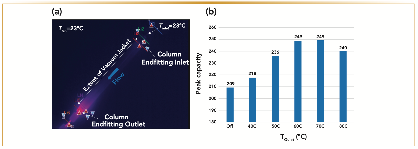
Accordingly, if the column is strictly operated under adiabatic conditions, the expected increase, ∆T, of the water temperature from the column inlet to the column outlet is expected to be ∆T = (1-∆T) ∆P/Cp = +18 °C. The red color at the column outlet end fitting revealed by the IR camera is an indication of heat leaks. It is noteworthy that the heat somewhat diffuses back towards the column inlet along a short section of the vacuum jacket. This IR camera image confirms that the whole column is not entirely thermally insulated and is still exchanging some heat with the surrounding laboratory air environment. The same phenomenon occurs at the column inlet when the imposed inlet temperature is above laboratory temperature. The overall result is a measurable loss of column performance caused by the presence of undesirable radial temperature gradients at both the inlet and the outlet regions of the column. The mechanism underlying this performance loss was previously proposed in a short communication (24).
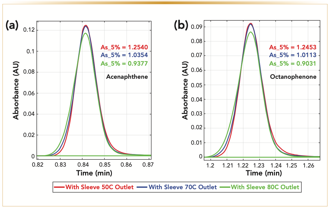
A physical solution to this problem is proposed and consists of placing an end nut heater at the column outlet in direct contact with the exposed SS surface of the outlet end fitting. The anticipated effect is to refocus the distorted peak shape as much as possible. The graph in Figure 5 considers the case where the temperature of the inlet mobile phase is fixed at 50 °C. The experimental section gives all the experimental details regarding the gradient conditions and the measurement of the reported peak capacity. The temperature, Toutlet, imposed by the outlet end nut heater was then increased stepwise from room temperature (“off” or passive) to 40, 50, 60, 70, and 80 °C. The most remarkable result is that the observed peak capacity passes through a maximum (249) for Toutlet = Toutlet,opt ~60–70 °C. The gain of peak capacity relative to that observed for the standard UHPLC–MS system (117) is now equal to +113%, close to the maximum of +116% expected theoretically. Overall, this is because of 1) the drastic reduction of the post-column sample dispersion from approximately 13 μL2 down to 0.3 μL2 and 2) the elimination of the negative effect of radial temperature gradients on column performance. The proposed explanation is as follows: when Toutlet is not sufficiently high (<60 °C), the temperature of the bed in the inlet and outlet regions of the column is more prominent in the center than in the wall region, and the loss of column performance is maximum. When Toutlet is optimum (~70 °C), the wall temperature is higher than the bed temperature at the column outlet (that is, the direction of the heat flow is reversed ature of the bed in the inlet and outlet from outside to inside). The initial peak distortion occurring at the column inlet is somewhat compensated at the column outlet according to a refocusing phenomenon (27–29), leading to nearly symmetric peaks. Finally, if Toutlet is too high (>75 °C), the heat flow imposed in the outlet region of the column is too large and overcompensates for the initial peak tailing (the peaks are then fronting). This mechanistic interpretation is well supported by 1) the calculation of the radial temperature profiles at the column outlet (Figure 6), according to the simulation approach described in the method section, which reveals that the amplitude of the radial temperature gradient is minimized for Toutlet ~70 °C and 2) from the evolution of the peak asymmetry (from tailing to symmetrical, and to fronting) observed under isocratic elution when increasing Toutlet from 50 °C to 80 °C (Figure 7).
FIGURE 6: Calculation of the radial temperature profiles across the diameter (2.1 mm) of the packed bed at the column outlet (z = 10 cm) for three different outlet end nut temperatures (Toutlet = 60, 70, and 75 °C) and fixed Tinlet = 50 °C. Note the quasi-flat temperature profile when the optimum outlet end nut temperature is set at 70 °C.
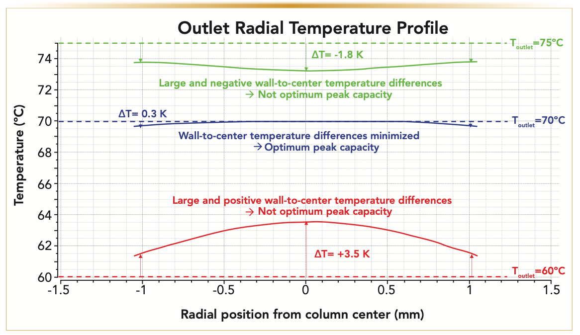
FIGURE 7: Experimental variation of the peak asymmetry (at 5% peak height) of (a) acenaphthene and (b) octanophenone eluted under isocratic conditions (see details in the experimental section) as a function of the outlet end nut temperature (Toutlet = 50, 70, and 80 °C) for Tinlet = 50 °C. Note the progressive evolution of the peak shape from tailing to fronting when increasing the heat flux from the column outlet wall to the packed bed. Quasi-symmetric peaks are observed at the optimum temperature of 70 °C.
Application and User Benefits
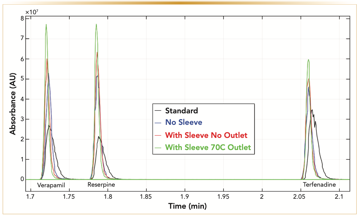
In this section, we illustrate the practical advantage of performing gradient elution with the modified UHPLC–MS system. The experimental section details the experimental conditions (column, gradient, flow rate, nature and concentration of the samples injected, and temperatures). In particular, Figure 8 compares the observed peak shapes (MS detection, MRM mode, and the total ion count) of three of the seven analyte products (the precursor ions are verapamil, reserpine, and terfenadine), which are recorded under the same four UHPLC–MS configurations as those discussed in the previous section (see Figure 4). After complete system modifications (from “standard” to “with sleeve 70 °C outlet”), it is remarkable that the peak widths are virtually reduced by a factor of two for all the compounds injected irrespective of their elution time. The total ion chromatogram in Figure 8 also confirms that the insulation of the column using a VJ and the application of heat at the column outlet participate both to further increase the resolution power and the sensitivity of the very same LC gradient method.
FIGURE 8: Application: LC–MS gradient chromatograms of a pharmaceutical sample mixture (See experimental section and Table I for the gradient conditions) recorded for the same four system configurations as those described in Figure 3. Note the constant reduction of the peak widths of verapamil, reserpine, and terfenadine compounds from the “Standard” to the “No sleeve,” “With the sleeve,” and to the “With sleeve and opt outlet T” system configurations.
Conclusion
In this work, a research prototype UHPLC–MS system was built to significantly improve the resolution performance compared to conventional UHPLC–MS systems. The improved system integration between the column outlet and the API source was made possible by replacing the LC oven with a column support placed directly against the API enclosure. In the absence of the column oven, maintaining the full integrity of the column efficiency consisted of wrapping the column with a vacuum jacket and delivering a well-controlled heat flow at the exposed outlet of the column. At pressure drops of about 12,000 psi, the temperature of the outlet end nut heater should be approximately 20 °C higher than the inlet temperature imposed by the active eluent preheater for maximum column performance. Additionally, the risk of eluent leaks at the column inlet and outlet and poor data reproducibility caused by the improper manual column installation and the aging of column-to-tube connections at very high pressures were avoided by adopting an easy-to-use cam-actuated mechanism for the column installation.
In conclusion, the overall relative increase of the peak capacity observed was quantitatively interpreted from the combination of the drastic reduction of the post-column sample dispersion (13 μL2 → 0.3 μL2) along with the elimination of most of the radial temperature heterogeneities (∆T < 0.3K) across the packed bed diameter by adjusting the temperature of the column outlet (Toutlet – Tinlet ~ 20 °C at ∆P ~12,000 psi and Fv = 0.6 mL/min).
Acknowledgments
The authors would like to sincerely thank Thomas McDonald, Michael Fogwill, Joseph Michienzi, Susan Abbatiello, Robert Plumb, and Nikunj Tanna (Waters Corporation) for their constant technical and engineering suggestions and fruitful discussions pertaining to this research project.
References
(1) C. Dass, in Fundamentals of Contemporary Mass Spectrometry (John Wiley and Sons, Hoboken, NJ, 2007).
(2) F. Regnier and G. Huang, J. Chromatogr. A 750, 3–10 (1996).
(3) J. Ermer and P.-G. Kibat, Pharm. Sci. & Technol. Today 1, 76–82 (1998).
(4) J. Ermer and M. Vogel, Biomed. Chromatogr. A 14, 373–383 (2000).
(5) W. Niessen, J. Chromatogr. A 1000, 413–436 (2003).
(6) I. Wilson, R. Plumb, J. Granger, H. Major, R. Williams, and E. Lenz, J. Chromatogr. B 817, 67–76 (2005).
(7) D. Guillarme, J. Schappler, S. Rudaz, and J.-L. Veuthey, TrAC 29, 15–27 (2010).
(8) G. Pocsfalvi, C. Stanly, I. Fiume, and K. Vekey, J. Chromatogr. A 1439, 26–41 (2016).
(9) F. Jeanneret, D. Tonoli, M. Rossier, M. Saugy, J. Boccard, and S. Rudaz, J. Chromatogr. A 1430, 97–112 (2016).
(10) E. Farsang, D. Guillarme, J.-L. Veuthey, A. Beck, M. Lauber, A. Schmudlach, and S. Fekete, J. Pharm. Biomed. Anal. 185, 113207 (2020).
(11) S. Popovici, W. Kok, and P. Schoenmakers, J. Chromatogr. A 1060, 237–252 (2004).
(12) K. Fountain, U. Neue, E. Grumbach, and D. Diehl, J. Chromatogr. A 1216, 5979–5988 (2009).
(13) F. Gritti, C. Sanchez, T. Farkas, and G. Guiochon, J. Chromatogr. A 1217, 3000–3012 (2010).
(14) F. Gritti and G. Guiochon, J. Chromatogr. A 1217, 7677–7689 (2010).
(15) F. Gritti and G. Guiochon, J. Chromatogr. A 1218, 4632–4648 (2011).
(16) S. Buckenmaier, C. Miller, T. van de Goor, and M. Dittmann, J. Chromatogr. A 377, 64–74 (2015).
(17) G. Desmet and K. Broeckhoven, TrAC 119, 115619 (2019).
(18) F. Gritti, T. McDonald, and M. Gilar, J. Chromatogr. A 1591, 110–119 (2019).
(19) H.-J. Lin and Sc. Horvath, Chem. Eng. Sci. 36, 47–55 (1981).
(20) F. Gritti and G. Guiochon, Anal. Chem. 80, 5009–5020 (2008).
(21) F. Gritti and G. Guiochon, Anal. Chem. 80, 5009–5020 (2008).
(22) K. Kaczmarski, F. Gritti, J. Kostka, and G. Guiochon, J. Chromatogr. A 1216, 6575–6586 (2009).
(23) F. Gritti, LCGC North Am. 36(6), 18–23 (2018).
(24) F. Gritti, LCGC North Am. 32(5), 8–13 (2019).
(25) F. Gritti, M. Gilar, and J. Jarrell, J. Chromatogr. A 1444, 86–98 (2016).
(26) F. Gritti, M. Gilar, and J. Jarrell, J. Chromatogr. A 1456, 226–234 (2016).
(27) D. Roper and E. Lightfoot, J. Chromatogr. A 702, 39–80 (1995).
(28) N. Lambert, S. Miyazaki, M. Ohira, N. Tanaka, and A. Felinger, J. Chromatogr. A 1473, 99–108 (2016).
(29) F. Gritti, M. Dion, A. Felinger, and M. Savaria, J. Chromatogr. A 1567, 164– 176 (2018).
ABOUT THE CO-AUTHORS
Fabrice G. Gritti is a Principal Consulting Scientist in the Instrument/Core Research/Fundamentals Department at Waters Corporation in Milford, Massachusetts.

Sornanathan Meyyappan is a Research Mechanical Engineer II at Waters Corporation in Milford, Massachusetts.

Wade P. Leveille is a Principal Mechanical Engineer working for Waters Corporation in Milford, Massachusetts.

Jason Hill is a Principal Research Scientist at Waters Corporation in Milford, Massachusetts.

ABOUT THE COLUMN EDITOR
David S. Bell is a Research Fellow in Research and Development at Restek. He also serves on the Editorial Advisory Board for LCGC and is the Editor for “Column Watch.” Over the past 20 years, he has worked directly in the chromatography industry, focusing his efforts on the design, development, and application of chromatographic stationary phases to advance gas chromatography, liquid chromatography, and related hyphenated techniques. His main objectives have been to create and promote novel separation technologies and to conduct research on molecular interactions that contribute to retention and selectivity in an array of chromatographic processes. His research results have been presented in symposia worldwide, and have resulted in numerous peer-reviewed journal and trade magazine articles. Direct correspondence to: LCGCedit@mmhgroup.com.


Common Challenges in Nitrosamine Analysis: An LCGC International Peer Exchange
April 15th 2025A recent roundtable discussion featuring Aloka Srinivasan of Raaha, Mayank Bhanti of the United States Pharmacopeia (USP), and Amber Burch of Purisys discussed the challenges surrounding nitrosamine analysis in pharmaceuticals.
Extracting Estrogenic Hormones Using Rotating Disk and Modified Clays
April 14th 2025University of Caldas and University of Chile researchers extracted estrogenic hormones from wastewater samples using rotating disk sorption extraction. After extraction, the concentrated analytes were measured using liquid chromatography coupled with photodiode array detection (HPLC-PDA).


