Generic UHPLC Method for the Simultaneous Analysis of Compounds with a Wide Range of Polarities
LCGC Asia Pacific
Appropriate analytical methods are required to evaluate the presence, metabolism, degradation, and removal of specific compounds in complex mixtures. There is an increasing demand to analyze samples with a wide range of polarities in a variety of applications, including environmental analysis, biomarker discovery, and proteomics. Multiple analyses on complementary columns are often needed to cover the separation of all compounds with a large difference in polarity. This article describes a generic method involving an ultrahigh‑pressure liquid chromatography (UHPLC) system equipped with two external switching valves to connect hydrophilic interaction liquid chromatography (HILIC) and reversed-phase LC columns in series for the sequential analysis of polar and apolar compounds.
Glenn Loos1, Monika Dittmann2, Konstantin Shoykhet2, Gert Desmet3, and Deirdre Cabooter1
1KU Leuven - University of Leuven, Department for Pharmaceutical and Pharmacological Sciences, Pharmaceutical Analysis, Leuven, Belgium, 2Agilent Technologies R&D, Waldbronn, Germany, 3Vrije Universiteit Brussel, Department of Chemical Engineering, Brussel, Belgium.
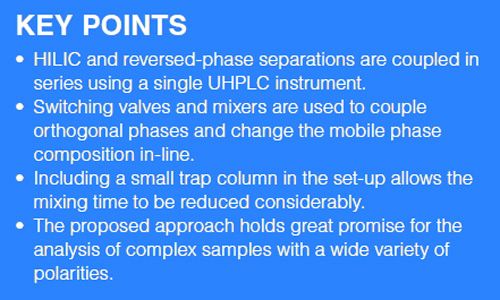
Appropriate analytical methods are required to evaluate the presence, metabolism, degradation, and removal of specific compounds in complex mixtures. There is an increasing demand to analyze samples with a wide range of polarities in a variety of applications, including environmental analysis, biomarker discovery, and proteomics. Multiple analyses on complementary columns are often needed to cover the separation of all compounds with a large difference in polarity. This article describes a generic method involving an ultrahighâpressure liquid chromatography (UHPLC) system equipped with two external switching valves to connect hydrophilic interaction liquid chromatography (HILIC) and reversed-phase LC columns in series for the sequential analysis of polar and apolar compounds. The method was successfully applied to separate 32 pharmaceutical compounds with a wide range of polarities, which could be useful for analyzing pharmaceutical compounds in the environment.
The number of complex samples emerging in different fields of analysis, such as environmental studies, biomarker discovery, and proteomics, is increasing rapidly (1–3). As a result of the presence of metabolites, transformation and degradation products, these samples typically display a large variety in polarity. To analyze such complex samples, multiple separations operating under different separation conditions are required. In principle, and provided the number of compounds in the sample is not too large, such analyses can be achieved by injecting the same sample several times on different columns operating under varying conditions (4–6). This approach requires the development of adequate separation methods for each analysis on each individual column. Apart from the fact that each analysis will require a new sample injection (which can be problematic when only limited sample is available), the original sample composition will not necessarily be compatible with the solvent conditions required for each analysis. A switch in sample solvent composition will be required in this case, making the approach difficult to automate.
Two-dimensional approaches (2D LC), where columnâswitching techniques are used to transfer fractions from a first to a second dimension column automatically, have proven powerful to separate complex samples (7). This is especially the case when columns operating under largely differing separation mechanisms, such as reversedâphase liquid chromatography (LC) and hydrophilic interaction chromatography (HILIC) are considered (8–10). When first and second dimension columns are coupled on-line, all fractions eluting from the first dimension are immediately analyzed in the second dimension. This can put strong demands on the methods in terms of column dimensions and flow rates when both columns operate under strongly differing mobile phase conditions. In some cases this can lead to dilution problems resulting in sensitivity issues and methods being used sub-optimally (11). The outcome of the separation, however, presents itself as a combination of chromatograms that require dedicated analysis software, making 2D approaches currently less interesting for routine analyses. As a more up-front alternative to on-line 2D approaches, the serial coupling of different separation conditions has been suggested (12–16). This approach entails splitting the sample on-line in a limited number of fractions that are sequentially analyzed on a second column under different separation conditions. Since the individual separations are performed in sequence, they are visualized in a single chromatogram amenable for direct analysis and interpretation.
When combining separation mechanisms operating under largely differing mobile phase conditions, both 2D and serially coupled approaches suffer from the problem that an on-line change in mobile phase is required before any subsequent separation can be commenced. A number of set-ups for the on-line changing or mixing of mobile phases in between analyses have been described in the literature (12,14,15). However, most of the proposed set-ups require elaborate instrumentation with multiple trap columns, solvent delivery pumps, and switching valves that often involve multiple system controllers, making it challenging to implement these set-ups routinely.
Very recently, we proposed a novel set-up for the on-line coupling of HILIC and reversed-phase LC columns in series to separate a sample consisting of compounds with a wide range of polarities (17). The set-up was entirely made up of commercially available equipment that could be controlled using the system’s software. A UHPLC system was equipped with two switching valves that were used to couple HILIC and reversed-phase LC columns either in series or in parallel to the system. The sample was first injected onto the HILIC column. The apolar compounds that were not retained on this column and eluted close to the void of the HILIC column were redirected towards a sample loop by changing the configuration of the valves. Meanwhile, the polar compounds were retained and separated on the HILIC column. Once the separation of the polar compounds on the HILIC column was completed, the configuration of the valves was altered again to redirect the apolar compounds from the sample loop to the reversedâphase column.
Commercially available mixers were integrated into the set-up for the on-line conversion of the mobile phase composition between both analyses. This was done to ensure the apolar compounds would be trapped adequately on the top of the reversed-phase column before analysis. The entire analysis was performed on a single UHPLC system containing a single quaternary pump and a single detector. Since both HILIC and reversed-phase LC analyses were performed sequentially, the final separation of the polar and apolar compounds was displayed into a single chromatogram. The main drawback of the system was the large dwell volume generated by the mixers, manifesting itself as a large additional delay time between the analysis of the polar and apolar compounds and increasing the total analysis time significantly (17).
In this study, we propose the simple addition of a small trap column to the set-up to intercept the compounds eluting from the mixers, before directing them to the analytical column. The small dimensions of the trap column and its concomitant low backpressure, allow operating the mixers in combination with the trap column at much higher flow rates than would be possible in combination with the analytical column. This leads to a significant reduction in delay time and hence overall analysis time as is demonstrated for the analysis of 32 pharmaceuticals with a wide range of polarities.
Experimental
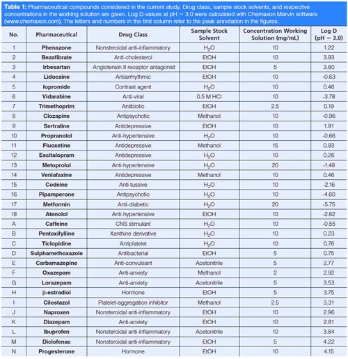
Chemicals and Columns: The following pharmaceuticals were selected as test compounds: atenolol, bezafibrate, clozapine, diclofenac, pipamperone, progesterone, sulphamethoxazole, metformin hydrochloride, and β-estradiol were from SigmaâAldrich; diazepam, propranolol, and carbamazepine were from Alpha Pharma; ticlopidine was from Sanofi; lorazepam from Fagron; Ibuprofen and lidocaine were from Certa; Naproxen was from Acros; Sertraline was from Apex Pharma; and escitalopram and venlafaxine were from Nodcar. Cilostazol, caffeine, codeine phosphate, metoprolol, trimethoprim, vidarabine, oxazepam, and iopromide were available in the lab as USP reference standards (Rockville, MD, USA), while pentoxyphylline was available as an EDQM reference standard (Strasbourg, France). Fluoxetine, irbesartan, and phenazone were available in the laboratory. These compounds were selected to represent common pharmaceuticals with a wide range of polarities, as can be witnessed from their log D-values that are displayed in Table 1. Log D-values at pH 3.0 were calculated with Chemaxon Marvin software (www.chemaxon.com).
Acetonitrile (HPLC grade) and ammonium acetate were from Fisher Chemical, ethanol (EtOH) was from VWR. Ammonium formate (Fluka) was purchased from SigmaâAldrich. Anhydrous acetic acid (100%) was from Merck and formic acid (99%) from Acros. High purity water (conductivity = 0.3 µS/cm, pH = 5.97) (H2O) was prepared in the laboratory using a Milli-Q gradient (Millipore) water purification system.
For the subdivision of the sample, a 100 mm × 2.1 mm, 1.7âµm dp Acquity BEH HILIC column (Waters) was used. Method development for the polar compounds was performed by evaluating their retention and separation on 100 mm × 2.1 mm, 1.7-µm dp Acquity BEH HILIC, Amide, and Cyano columns (Waters). For the method development of the apolar compounds, a 100 mm × 2.1 mm, 1.7âµm dp Acquity BEH C18 (Waters), a 100 mm × 2.1 mm, 1.7âµm dp Acquity polar embedded BEH (RP-18) (Waters), and a 100 mm × 2.1 mm, 1.8-µm dp Zorbax Eclipse Plus PhenylâHexyl columns (Agilent Technologies) were evaluated.
In the final set-up, a 100 mm × 3.0 mm, 1.8-µm dp Zorbax Eclipse Plus Phenyl-Hexyl column (Agilent Technologies) was used for the separation of the apolar compounds.
Two serially coupled 100 mm ×1.0 mm, 1.7-µm dp Acquity BEH HILIC columns (Waters) were used for the separation of the polar compounds. A 30 mm × 3.0 mm, 1.8-µm dp Zorbax Eclipse Plus Phenyl-Hexyl trap column (Agilent Technologies) was used to intercept the apolar compounds eluting from the mixers.
Apparatus: All experiments were executed on an Agilent Infinity UHPLC 1290 system (Agilent Technologies). The system consisted of a 1290 quaternary pump, a 1290 autosampler, and a 1290 diode array detector (DAD) with a 1.0 µL flow cell (path length: 10 mm). The system was equipped with two 9-port/8-position ultrahigh-pressure valves (max. pressure 1200 bar). System operation, valve configuration, data acquisition, and analysis were handled using Chemstation software (Agilent Technologies). All connections between pump, valves, columns, mixers, and detector were made using Viper tubing (Thermo Scientific) with an internal diameter of 75 µm and the shortest possible length. The mixing unit consisted of four serially coupled Jet Weaver mixers (Agilent) (17). Mixers with volumes of 380 µL (2×) and 1140 µL (2×) were used in the set-up, resulting in a total mixing volume of approximately 3.04 mL.
Methodology: Stock solutions of the compounds were prepared in a concentration between 2 mg/mL and 20 mg/mL in either water or an organic solvent (Table 1). A working solution for method development was prepared by mixing the appropriate amounts of solutions and then adding acetonitrile to a final volume of 1.5 mL with a final composition of ∼95% organic solvent. The concentrations of the compounds in this working solution can also be found in Table 1.
Subdivision of the Sample: Following the procedure elaborated in (17), a generic gradient was run on a HILIC column at a flow rate of 0.4 mL/min, using a detection wavelength of 210 nm and an injection volume of 1.0 µL. For this purpose, an isocratic hold of 95% acetonitrile for 5 min was followed by a gradient wherein the mobile phase composition varied from 95% acetonitrile to 50% acetonitrile in 10 min. The aqueous component of the mobile phase consisted of 10 mM ammonium formate, brought to pH 3.0 using formic acid. Subdivision of the sample into polar and apolar compounds was based on the retention obtained for the different compounds under these conditions.
Method Development for the Polar and Apolar Compounds: After the subdivision of the sample into polar and apolar compounds, a method was developed for the apolar compounds on reversed-phase columns and for the polar compounds on HILIC columns. For this purpose, generic scouting runs were conducted on each available stationary phase (see Chemicals and Columns section) at a flow rate of 0.4 mL/min to identify the most promising separation conditions. The organic modifier percentage was varied between 5% and 95% acetonitrile for the reversed-phase stationary phases and between 95% and 50% acetonitrile for the HILIC stationary phases in 10 min. The pH-value of the aqueous component of the mobile phase was altered between 3.0 and 6.8 using ammonium formate and ammonium acetate, respectively, with a total concentration of 10 mM. The best runs for the separation of the polar compounds on HILIC columns and for the apolar compounds on reversedâphase columns were selected as the runs that led to the largest number of separated peaks with the highest critical pair resolution. These runs were subsequently optimized by varying the gradient parameters (start and end concentration of the organic modifier, gradient time), the flow rates, and the column lengths (18,19).
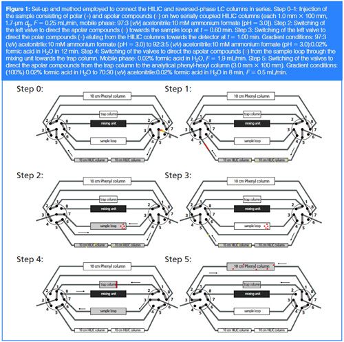
Hyphenation of the Final Obtained Methods: The HILIC stationary phase leading to the best separation of the polar compounds was subsequently serially coupled to the stationary phase leading to the best separation of the apolar compounds using the set-up shown in Figure 1.
The entire sample (containing both polar and apolar compounds) was first injected on the HILIC columns (step 0–1, Figure 1) operated at a flow rate of 0.25 mL/min and using a mobile phase composition of 97:3 (v/v) acetonitrile:10 mM ammonium formate (pH 3.0). While the polar compounds were retained on the HILIC columns, the configuration of the valves was changed at t = 0.60 min to direct the apolar compounds eluting in the void of the HILIC columns towards a sample loop (step 2, Figure 1). Once the apolar compounds were contained in the sample loop, the configuration of the valves was changed again at 1.00 min to direct the separated polar compounds eluting from the HILIC column towards the detector (step 3, Figure 1). For this purpose, the mobile phase composition was changed from 97:3 (v/v) acetonitrile:10 mM ammonium formate (pH 3.0) to 92:3:5 (v/v) acetonitrile:10 mM ammonium formate (pH 3.0):0.02% formic acid in H2O in 12 min. After this, the configuration of both valves was altered to direct the apolar compounds from the sample loop through the mixing unit towards the trap column. A new mobile phase (consisting of 0.02% formic acid in H2O) was used at a high flow rate (1.9 mL/min) to dilute the acetonitrile plug containing the apolar compounds, allowing the apolar compounds to be adequately retained on the trap column (step 4, Figure 1). Finally, the configuration of the valves was changed one last time to couple the trap column in series with the analytical reversedâphase column for the separation of the apolar compounds (step 5, Figure 1). For this purpose, the mobile phase composition was changed from 0.02% formic acid in H2O to 70:30 (v/v) acetonitrile:0.02% formic acid in H2O in 8 min at a flow rate of 0.5 mL/min.
Results and Discussion
Subdivision of the Sample: Following the method expounded in (17), the sample was subdivided into polar and apolar compounds based on their retention obtained on the HILIC column, using the generic gradient described above. All compounds eluting in or near the void of the column were classified as apolar compounds. These compounds are denoted with letters A–N in Table 1. All other compounds with clear retention on the HILIC column (denoted with numbers 1–18 in Table 1) were classified as polar.
Method Development for the Polar and Apolar Compounds: Initial method development efforts were performed on 2.1 mm × 100 mm columns, because a large selection of column selectivities were available in the laboratory in these dimensions. To obtain a satisfactory separation for all polar compounds, two identical 2.1 mm × 100 mm HILIC columns were coupled in series. A gradient separation wherein the mobile phase composition was first held at 97:3 (v/v) acetonitrile:10 mM ammonium formate (pH 3.0) for 4 min and subsequently varied to 92:3:5 (v/v) acetonitrile:10 mM ammonium formate (pH 3.0):0.02% formic acid in H2O in 12 min at a flow rate of 1.1 mL/min was used to adequately separate all polar compounds. For the apolar compounds, baseline separation was obtained on a 2.1 mm × 100 mm phenyl-hexyl column operating under gradient conditions wherein the solvent composition was altered from (100%) 0.02% formic acid in H2O to 70:30 (v/v) acetonitrile:0.02% formic acid in H2O in 8 min at a flow rate of 0.25 mL/min. Once the optimal separation conditions were identified for the polar and apolar compounds, the HILIC separation was converted to 1.0-mm i.d. column formats and the reversedâphase LC separation to a 3.0-mm i.d. column format by scaling the flow rates according to the column diameters. This was done to limit the volume of the acetonitrile-rich plug wherein the apolar compounds would elute from the HILIC column and ensure this acetonitrile-rich plug would be sufficiently diluted when passing through the mixing unit (17). The final separations obtained for the polar and apolar compounds on HILIC and reversed-phase LC columns, respectively, are shown in Figure 2.

Hyphenation of the Final Obtained Methods: To hyphenate these two methods, the set-up shown in Figure 1 was used to redirect the apolar compounds from the HILIC column towards the sample loop. For this purpose, the configuration of the left valve was changed from the position shown in step 1 (Figure 1) to the position in step 2 (Figure 1) just before the apolar compounds started eluting from the HILIC column. To accurately determine the timing upon which the configuration of this valve should be switched, the sample was first injected in its entirety and under the optimized mobile phase conditions on the coupled HILIC columns (obtained separation shown in Figure 3). This allowed the window wherein the apolar compounds eluted from these columns (and hence the timing upon which the valve should be switched) to be defined between 0.60 min and 1.00 min (denoted by the red frame).

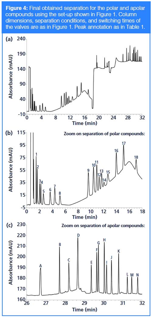
The entire sample was subsequently injected on the HILIC columns again, but this time the configuration of the left valve was actually altered from the position in step 1 to step 2 (Figure 1) at 0.60 min to direct the apolar compounds to the sample loop and from the position in step 2 to step 3 (Figure 1) at 1.00 min to ensure the polar compounds would be directed towards the detector once they started eluting from the HILIC column. It has already been demonstrated (17) that changing the configuration of the valves during the HILIC separation has no effect on the separation of the polar compounds (see also Figure 4). Note that under the specified conditions (F = 0.25 mL/min), the apolar compounds will elute in a solvent plug with a volume of ∼100 µL (see also below). To ensure the apolar compounds would be adequately captured in the sample loop, the volume of the sample loop was chosen sufficiently large enough (200 µL) to avoid the apolar compounds from eluting towards the detector before the configuration of the left valve was switched back to the position in step 3.
After elution of the polar compounds from the HILIC column, the configuration of both valves was switched to the configuration shown in step 4 of Figure 1 to redirect the apolar compounds from the sample loop towards the trap column. The apolar compounds were dissolved in a large plug of acetonitrile at this stage. The volume of this plug can be roughly calculated from the applied flow rate on the HILIC columns, the percentage of acetonitrile in the HILIC mobile phase, and the switching times of the valves as 0.25 mL/min × 0.97 × (1.00–0.60 min) = 97 µL. To ensure the apolar compounds can be adequately withheld on the trap column, the amount of acetonitrile in this plug was reduced drastically. For this purpose, a mixing unit with a total volume of approximately 3 mL was coupled between the sample loop and the trap column. The mixing unit was prefilled with an aqueous mobile phase by coupling the mixing unit directly to the instrument and pumping 0.02% formic acid in H2O (pH ∼ 3.0) through it at a high flow rate (1 mL/min). The configuration of the valves was subsequently switched to the configuration in step 4 of Figure 1 and a high flow of 0.02% formic acid in H2O (1.9 mL/min) was applied to elute the apolar compounds towards the trap column. By prefilling the mixing unit with an aqueous solvent and using the same solvent to elute the apolar compounds from the sample loop towards the mixing unit, the acetonitrile-rich plug containing the apolar compounds was virtually sandwiched between two layers of aqueous solvent. The mixers allowed an adequate dilution of the acetonitrile-rich plug when passing through the mixing unit and before reaching the trap column. The low backpressure of both the mixing unit and the short trap column moreover ensured that the entire dilution process occurred at a high flow rate, reducing the delay time required to pass through the mixing unit to only 1.6 min
(3 mL/ 1.9 mL/min).
Finally, the configuration of the valves was altered one last time to the configuration shown in step 5 of Figure 1 to elute the apolar compounds from the trap column to the analytical column for separation.
The final separation obtained in this way is shown in Figure 4. Note that the separations that were previously obtained for the polar and apolar compounds separately in Figure 2 are nearly perfectly maintained in the coupled set-up, while the delay time caused by the mixing unit is drastically reduced by including a small trap column in the set-up to intercept the apolar compounds eluting from the mixing unit.
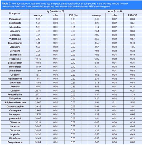
To verify whether the repeated valve and column switching would have an effect on the repeatability of the final obtained method, the same separation was executed six times successively. As can be deduced from Table 2, the repeatability of the retention times of all compounds was excellent, with a maximum variation of 0.4% relative standard deviation (RSD). For the areas, slightly larger variations were observed but in general these were still below 1.0% RSD. These findings suggest that the presented approach has potential to be used in routine applications.
Since HILIC and reversed-phase LC analyses are performed in series, the peak capacity of the overall separation can be calculated by adding the peak capacities of the individual separations. The individual peak capacities (np,RPLC and np,HILIC) were calculated as (20):

[1]
With tR,i the retention time of peak i and tR,i-1 the retention time of peak i-1 and σi the square root of the variance of peak i (σ²), related to the width of the peak. This leads to a peak capacity of np,HILIC = 61 for the HILIC separation and np,RPLC = 100 for the reversed-phase LC separation, resulting in a total peak capacity of np,total = 161. Such peak capacity can be considered as intermediate to typical peak capacities that are obtained under one-dimensional (1D) and 2D conditions.
Conclusions
A novel approach for the serial coupling of HILIC and reversed-phase LC is described. For this purpose, a UHPLC instrument is equipped with two switching valves that can be controlled using the system’s software. These valves are used to redirect apolar compounds that are not withheld on a HILIC column and hence elute near the void of this column towards a sample loop, where they are stored while the separation of the polar compounds on the HILIC column is performed. Once the separation of the polar compounds is complete, the switching valves are used to direct the apolar compounds from the sample loop through a mixing unit consisting of a number of serially connected mixers, wherein the sample solvent is modified to a large percentage of water. The mixing unit is connected to a small trap column to intercept the apolar compounds eluting from the mixing unit. In this way, the mixing unit can be operated at a high flow rate, reducing the delay time caused by the high dwell volume of the mixers considerably. The trap column is finally connected to an analytical column by switching the valves one more time to separate the apolar compounds on the analytical column.
The proposed set-up is shown to result in an adequate and repeatable separation of both polar and apolar compounds in the sample and can therefore potentially be used for routine applications. Intermediate peak capacities to 1D and 2D separations are obtained. This makes the proposed set-up a promising alternative for the analysis of samples of intermediate complexity containing compounds with a wide range of polarities, such as emerging micro-pollutants and their degradation or transformation products in environmental studies.
Acknowledgements
Agilent Technologies is kindly thanked for the gift of the UHPLC system through a University Relations Grant. The Research Foundation Flanders is acknowledged for financial support (Research Grant: 1509114N). Glenn Loos acknowledges the Ysebaert Devos Fund (Faculty of Pharmacy, KU Leuven) for financial support.
References
- M.G.M. Kok, G.W. Somsen, and G.J. De Jong, Trends Anal. Chem.61, 223–235 (2014).
- J.R. Griffiths, S. Perkins, Y. Connolly, L. Zhang, M. Holland, V. Barattini, et al., J. Chromatogr. A1232, 276–280 (2012).
- M. Meyer-Monath, C. Chatellier, D. Cabooter, F. Rouget, I. Morel, and F. Lestremau, Talanta 138, 231–239 (2015).
- R. Hirsch, T.A. Ternes, K. Haberer, A. Mehlich, and F. Ballwanz, J. Chromatogr. A815, 213–223 (1998).
- T.A. Ternes, M. Bonerz, N. Herrmann, L. Dirk, and E. Keller, J. Chromatogr. A1067, 213–223 (2005).
- P. Kubica, A. Kot-Wasik, A. Wasik, and J. Namiesï¢nik, J. Chromatogr. A1289, 13–18 (2013).
- P.J. Schoenmakers, G. Viv, and W.M.C. Decrop, J. Chromatogr. A1120, 282–290 (2006).
- Y.S. Ling, H.J. Liang, M.H. Lin, C.H. Tang, K.Y. Wu, M.L. Kuo, et al., Biomed. Chromatogr.28, 1284–1293 (2014).
- A. Mihailova, H. Malerød, S.R. Wilson, B. Karaszewskl, R. Hauser, E. Lundanes, et al., J. Sep. Sci.31, 459–467 (2008).
- K.M. Kalili and A. De Villiers, J. Chromatogr. A1289, 69–79 (2013).
- D.R. Stoll, X. Li, X. Wang, P.W. Carr, S.E.G. Porter, and S.C. Rutan, J. Chromatogr. A1168, 3–43 (2007).
- Y. Wang, X. Lu, and G. Xu, J. Sep. Sci.31, 1564–1572 (2008).
- S. Louw, A.S. Pereira, F. Lynen, M. Hanna-Brown, and P. Sandra, J. Chromatogr. A1208, 90–94 (2008).
- Y. Wang, R. Lehmann, X. Lu, X. Zhao, and G. Xu, J. Chromatogr. A1204, 28–34 (2008).
- M.P.Y. Lam, S.O. Siu, E. Lau, X. Mao, H.Z. Sun, P.C.N. Chiu, et al., Anal. Bioanal. Chem.398, 791–804 (2010).
- G. Greco, S. Grosse, and T. Letzel, J. Sep. Sci.37, 630–634 (2014).
- D. Cabooter, K. Choikhet, F. Lestremau, M. Dittmann, and G. Desmet, J. Chromatogr. A1372, 174–186 (2014).
- G. Desmet and D. Cabooter, LCGC Europe22, 70–77 (2009).
- D. Cabooter, D. Clicq, F. De Boever, F. Lestremau, R. Szucs, and G. Desmet, Anal. Chem.83, 966–975 (2011).
- K. Broeckhoven, D. Cabooter, S. Eeltink, and G. Desmet, J. Chromatogr. A1228, 20–30 (2012).
Glenn Loos obtained a Masters in biochemistry and biotechnology from the University of Antwerp (Belgium) and is currently conducting a PhD under the supervision of Deirdre Cabooter at the University of Leuven (KU Leuven). His research focuses on the development of new UHPLC and sample preparation methods for the analysis of pharmaceutically relevant contaminants in surface and wastewater samples.
Monika Dittmann joined HP (now Agilent Technologies) as an R&D scientist in 1988, after finishing her PhD and spending two years as a post-doc at UC Berkeley. In her career with HP/Agilent she has worked on the development of instruments and technologies in the fields of HPLC, capillary electrophoresis, capillary electro-chromatography, and micro-fluidics as a research scientist and project manager. Monika currently holds the position of Principal Scientist and works on the design and development of next generation HPLC systems.
Konstantin Shoykhet received his PhD in HPLC and CE in 1995 from the Institute for Physical Chemistry at the University of Saarland, Saarbrücken, Germany, under the supervision of Prof Dr. Heinz Engelhardt. He joined Hewlett-Packard in Waldbronn, Germany, in 1999, and now works as an expert scientist in the field of liquid separation technologies.
Gert Desmet heads the Department of Chemical Engineering at the Vrije Universiteit Brussel (VUB), Belgium. His research mainly focuses on the miniaturization and automation of separation methods, as well as on the investigation and the modelling of flow effects in chromatographic systems. He is the first or senior author of over 250 peer-reviewed papers and 11 patent applications. He is a past chair of the Chemistry Panel of the Flemish National Science Fund (FWO), and associate editor of Analytical Chemistry, a journal of the American Chemical Society. He is also a member of the editorial board of J. Chrom. A and LCGC Europe. In 2016, he received an ERC Advanced grant.
Deirdre Cabooter received a PhD in chemical engineering under the supervision of Gert Desmet at the VUB in 2009. After two and a half years of postdoctoral work at the VUB and the Department of Chemistry and Polymer Science of Stellenbosch University (South Africa), she obtained an assistant professor position at the Department of Pharmaceutical and Pharmacological Sciences of KU Leuven in 2011. Her research interests include the fundamental evaluation of novel supports in chromatography, the analysis of complex samples in diverse fields of application, retention modelling, and solutions for automated method development.

Determining the Effects of ‘Quantitative Marinating’ on Crayfish Meat with HS-GC-IMS
April 30th 2025A novel method called quantitative marinating (QM) was developed to reduce industrial waste during the processing of crayfish meat, with the taste, flavor, and aroma of crayfish meat processed by various techniques investigated. Headspace-gas chromatography-ion mobility spectrometry (HS-GC-IMS) was used to determine volatile compounds of meat examined.
University of Tasmania Researchers Explore Haloacetic Acid Determiniation in Water with capLC–MS
April 29th 2025Haloacetic acid detection has become important when analyzing drinking and swimming pool water. University of Tasmania researchers have begun applying capillary liquid chromatography as a means of detecting these substances.
Using GC-MS to Measure Improvement Efforts to TNT-Contaminated Soil
April 29th 2025Researchers developing a plant microbial consortium that can repair in-situ high concentration TNT (1434 mg/kg) contaminated soil, as well as overcome the limitations of previous studies that only focused on simulated pollution, used untargeted metabolone gas chromatography-mass spectrometry (GC-MS) to measure their success.

.png&w=3840&q=75)

.png&w=3840&q=75)


.png&w=3840&q=75)


.png&w=3840&q=75)


