The LCGC Blog: Split Later and the Case of the Infinite Dilution Tube
E-Separation Solutions
No, this isn't a new detective novel, in fact its two concepts which were "coined" by my good friend John Hinshaw during a recent CHROMacademy webcast which we presented together on sample introduction for capillary GC.
No, this isn’t a new detective novel, in fact its two concepts which were ‘coined’ by my good friend John Hinshaw during a recent CHROMacademy webcast which we presented together on sample introduction for capillary GC.
I have to admit to laughing out loud at the term ‘Split Later’ which John proposed as a better term to actually describe spitless injection. It brought home to me that, no matter how long we have been involved with a technique, there is always merit in looking at it from a different angle or seeking better language to describe it.
So – for all Gas Chromatographers, here’s a summary of what I learnt during that webcast session, mixed with some tips of my own for successful trace analysis.
We probably all know that splitless injection is used for analysis of trace and minor components within the sample – where the use of on instrument dilution (i.e. split injection) would render the analysis unable to achieve the required detection limits.
Most of us also probably know that we achieve splitless injection by having the split valve closed during the injection in order to entrain the entire sample onto the column. However – herein lies the issue with the term ‘splitless’. In fact, for the technique to be properly employed – at some point after the injection we need to open the split valve – hence Johns ‘Split Later’ terminology. Beautifully descriptive and much less confusing – even after 28 years of carrying out this type of analysis on an almost daily basis!
So – why split later? Why do we need to open the split vent at all? Well this is where the Infinite Dilution Tube comes into play. We tend to think that our liquid samples form a ‘plug’ of vapour which is introduced into the inlet and swept, as a contiguous plug, into the column over a period of time. Which would be fine if we were considering an HPLC injection - however we need to be mindful that we are working in the vapour phase – where mixing occurs much more readily. The carrier acts to sweep to our sample plug onto the column, however due to the high level of mixing, the sample actually experiences dilution over a very long period of time within the inlet (i.e. we never really get the entire sample or sample solvent onto the column).
This actually causes problems with our chromatography and can lead to rising or excessively noisy baselines within chromatograms and large, tailing, solvent peaks, which often ‘collide’ with early eluting analytes. All of these symptoms are caused by the slow ‘bleed’ of sample components and the sample solvent from the inlet over time.
These problems can be very simply remedied by opening the split valve to allow the lingering sample components to escape the liner and not bleed into the column. The timing of this ‘purge-on’ event is important, as we need to achieve a balance between not losing sample (split valve opens too early) and avoiding the symptoms described above which re associated with the split valve being opened too late or not at all.
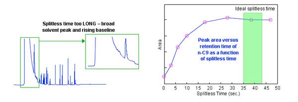
Typically the ‘purge’ or ‘splitless’ time is determined empirically. Several injections are made and the peak areas of early, mid and late eluting peaks plotted against splitless times which start at around 30 seconds and which are increased in 10 or 20 second increments for each subsequent injection. The results will look something like those shown in Figure 1 – and the optimum splitless time safely onto the plateau of the curve, where we are confident that we are not losing any sample and peak areas are reproducible.

Figure 1: Problems with extended splitless operation in capillary GC and a plot of peak area versus splitless time to determine the optimum splitless time which will overcome the solvent tailing issues shown.
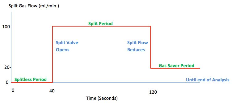
The split flow which is applied at the end of the of the splitless time is somewhat arbitrary – however, it’s a good idea to quickly empty the inlet of residual materials so we tend to use split ratios of 100:1 if possible.
For those of us using helium as carrier gas, it’s worthwhile switching to ‘gas saver’ mode after one or two minutes in split mode to conserve helium for the remainder of the analysis.
Figure 2 shows a ‘timeline’ of events for a splitless (later!) injection which shows the various split valve events alongside some hypothetical times and carrier gas flow rates through the inlet.

Figure 2: Timeline for the split flow during a typical splitless GC injection
For more information – contact either
Bev () or Colin (colin@crawfordscientific.com).
For more tutorials on LC, GC, or MS, or to try a free LC or GC troubleshooting tool, please visit www.chromacademy.com

.png&w=3840&q=75)

.png&w=3840&q=75)


.png&w=3840&q=75)


.png&w=3840&q=75)

