The LCGC Blog: Capillary GC Liner Selection Guide
E-Separation Solutions
This blog attempts to provide an impartial guide to liner selection which is representative of the considerations in modern capillary GC.
I’ve always thought that a simple guide to liner selection for capillary gas chromatography was a good idea. The internet is packed with information from vendors on which type of liner to use, however there is a tendency to push their latest greatest design, or explain the function of a whole bunch of historical designs which frankly are no longer required, due to improvements in instrument or liner design.
So, this blog attempts to provide an impartial guide to liner selection which is representative of the considerations in modern capillary GC.
A liner is typically constructed of quartz glass and the tubular device resides within the vaporising GC inlet in order to perform one, or a combination of, the following functions;
- Provide an inert area in which the volatilise of the sample can occur
- Facilitate transfer of the sample either into the column or out of the split line
- Ensure efficient, quantitative transfer of all sample components into the column
And here is what we need to avoid in selecting an appropriate liner;
- Contributes to sample degradation
- Contributes unwanted secondary retention (adsorption) mechanisms for some or all sample components
- Contributes excess dead volume into the system which leads to unnecessary peak broadening (loss of efficiency)
- Gives rise to sample backflash through inadequate internal volume
I’ve used some specific experiment examples below to give an indication of the possible thought processes when selecting an appropriate liner;
Split Injection
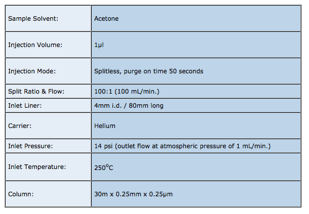
The residence time of the sample within the liner (t), under the split injection conditions shown above is given by:


Now;

The default liner for splitless injection is usually a straight through deactivated liner with no packing material as shown here;

As we have seen, splitless injections occur quickly with the vapourised sample being rapidly transported into the column, resulting in narrow (efficient) analyte peaks.
A straight through liner allows rapid sample vapour transfer into the column. One should take care to ensure the position of the column within the inlet is in compliance with manufacturer’s instructions.
The liner should be de-activated in order to remove any silanol species on the quartz (silica) glass surface which may give rise to secondary interactions between polar analytes and the liner surface. Secondary interactions result in a reduction in sensitivity for the analytes involved, poor peak area reproducibility and/or peak tailing.
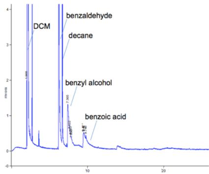
Good peak shape for non-polar analytes and tailing of polar analytes indicates that secondary retention mechanisms are in-play
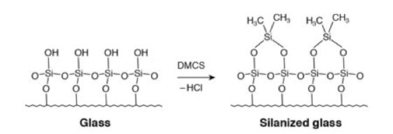
Typical deactivation reaction of the quartz glass surface using DMCS
Manufacturers of liners and capillary GC columns have developed highly sophisticated de-activation treatments to ensure the very lowest levels of analyte adsorption and the best peak shapes possible.
If peak area reproducibility is poor or if inlet discrimination is suspected, glass wool may be added to assist with the sample volatilisation and mixing.

Deactivated quartz glass
Deactivated quartz wool, positioned so the autosampler syringe penetrates the plug during injection. Mass and density of glass wool is important. Held in place by the baffles either side of the plug
Open bottom deign to ensure fast mass transfer of sample vapours into the column
Some deigns have a quartz glass ‘button’ on the lower rim to stop the liner from resting onto the bottom surface of the inlet – to avoid peak shape deformations and poor reproducibility in some instrument designs
Higher boiling analytes may pass the split point (column entrance) in the liquid state or, following vaporisation associated with the liner walls rather than the middle of the liner (where the column is positioned) and be lost from the split line, which gives a falsely low response for later eluting compounds.
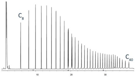
All analytes are present in this sample of n-alkanes at equal concentration.
Lower analyte response for higher mass analytes is caused by inlet discrimination.
The use of a plug of deactivaed glass wool, positioned within the liner so as to wipe the tip of the injection syringe during injection, gives the following advantages;
- Promotes mixing to improve injection reproducibility and minimise mass discrimination due to wall effects
- Provides a large surface area from which higher boiling analytes can evolve into the gas phase, again reducing mass discrimination
- Wipes the needle tip and prevents needle discrimination due to condensation of higher boiling analytes onto the needle outer surface
- Prevents the analyte from contacting the bottom of the liner (preventing poor peak shape and compromised quantitation when dealing with thermally labile analytes)
- Prevents involatile materials (sample components / septum shards) from contaminating the inlet / column
Sometimes the use of deactivated quartz wool can cause issues with highly adsorptive compounds, in which case other liner packing’s such as carboxen and other highly inactive materials should be considered.
If the use of a glass wool plug doesn’t solve your problems with poor quantitative reproducibility or you are having problems with carryover – try the following quick check.
To calculate the liner volume (V) use

UNLESS the liner has baffles, glass wool or restrictions in which case your manufacturer should provide you with these details.
The density of the solvent is known and under the given temperature and pressure conditions we can calculate the volume of vapour formed on injection.

V1 = injection volume (µl), D = sample solvent density (g/mL), MW = molecular weight of sample solvent, T = inlet temperature (oC), Pi = inlet pressure, Po = atmospheric pressure

We don’t really need to do this as there are several good freely available calculators;
http://www.restek.com/images/calcs/calc_backflash.htm
http://www.sge.com/products/gc-lc-supplies/gc-supplies/gc-inlet-liners3#Tool
If the volume of sample vapour produced, exceeds the liner volume, then sample will be carried to, and deposited within, lower temperature parts of the GC tubing. This is sometimes referred to as ‘backflash’ and is primary cause of poor quantitative reproducibility and sample carry-over (when you get a mini version of your previous sample chromatogram in a blank injection).

Check that the volume of the sample vapour produced is less than 75% of the liner internal volume to ensure that backflash does not occur.
Under the conditions of our split method above, the volume of sample vapour produced is 583µl which is less than 75% of the total liner volume of 1005µl
Some folks like to use an upper gooseneck within the liner to restrict the flow of excess sample vapours out of the top of the liner – this approach should be avoided and steps taken to reduce the amount of sample vapour formed – i.e. reduce injection volume, change solvent or use a pressure pulse during the injection phase.
Splitless Injection
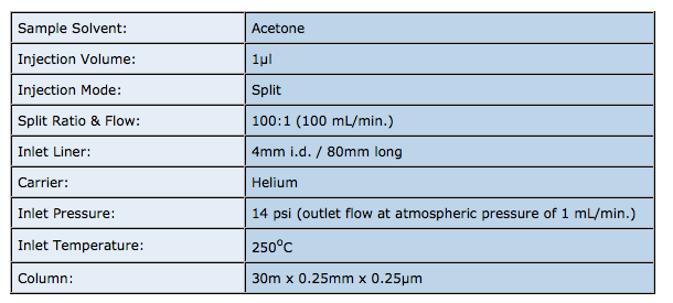
The residence time of the sample within the liner (t), under the splitless injection conditions shown above is given by:


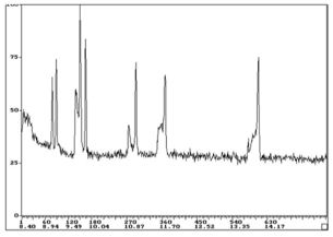
The theoretical vapour residence time of the sample within the inlet is now much longer in this splitless injection, as might be expected due to the much lower liner carrier gas flow rate. We need to protect the sample from contacting the lower, hot metal surface of the inlet, otherwise we get ‘chair shaped’ peak deformations as shown here and poor peak area reproducibility due to sample thermal decomposition.
So, typically, splitless liners have a lower gooseneck as shown here, which restricts access to the hot metal surfaces in the lower part of the liner and acts to ‘funnel’ the analyte components into the mouth of the capillary column.
For all of the reasons cited in the previous section, splitless injection liners also tend to be packed with deactivated glass wool to aid with sample mixing and to prevent discrimination effects. In splitless injection the glass wool also acts to protect the column from contamination by less volatile components of the sample, which would otherwise all be entrained into the head of the analytical column.

Many other liner designs are available, however in modern gas chromatography, those which are described above will satisfy the majority of applications.
For more information – contact either
Bev ([email protected]) or Colin ([email protected]).
The LCGC Blog: Historical (Analytical) Chemistry Landmarks
November 1st 2024The American Chemical Society’s National Historic Chemical Landmarks program highlights sites and people that are important to the field of chemistry. How are analytical chemistry and separation science recognized within this program?

.png&w=3840&q=75)

.png&w=3840&q=75)


.png&w=3840&q=75)


.png&w=3840&q=75)

