HILIC: A Critical Evaluation
This article, transcribed from an LCGC web seminar presented on January 29, 2013, by Davy Guillarme of the University of Geneva and the University of Lyon, explains how HILIC works and provides keys to using the technique effectively.
Introduction: Hydrophilic-interaction chromatography (HILIC) can be an excellent alternative to reversed-phase liquid chromatography (LC) for the separation of polar compounds, and thus is particularly attractive to separation scientists working in the pharmaceutical field. This article, transcribed from an LCGC web seminar presented on January 29, 2013, by Davy Guillarme of the University of Geneva and the University of Lyon, explains how HILIC works and provides keys to using the technique effectively.
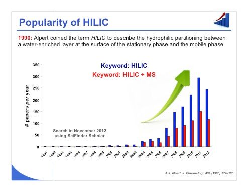
Slide 1: The term hydrophilic-interaction chromatography (HILIC) was coined at the beginning of the 1990s by Alpert to describe the hydrophilic partitioning between a water-enriched layer at the surface of the stationary phase and the mobile phase itself. This allowed retention of the most polar compounds, which is critical under reversed-phase liquid chromatography (LC) conditions. Slide 1 shows that the number of scientific papers published with the keyword HILIC has grown significantly during the last 5 years. It is also important to note that 50% of the published studies used mass spectrometry (MS) for detection. Indeed, we will see that MS sensitivity can be drastically enhanced compared to reversed-phase LC when working under HILIC conditions.
Next >
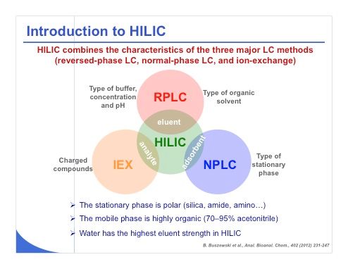
Slide 2: Briefly, HILIC combines some of the characteristics of the three major methods of LC (slide 2). For example, the mobile phase in HILIC is very close to a reversed-phase LC mobile phase. So the type of buffer, concentration, pH, and type of organic modifier look almost equivalent. However, HILIC is also very close to normal-phase LC in terms of stationary phase and generally HILIC is performed with a polar stationary phase, such as a silica, amide, or amino phase. Finally, the compounds that can be analyzed in HILIC are the same as those that can be analyzed by ion-exchange chromatography, namely charged compounds. This is why HILIC is a mix of these three different techniques.
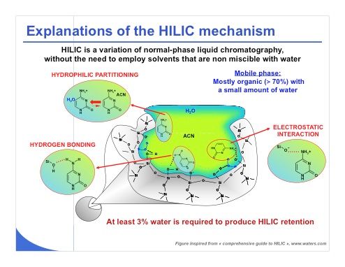
Slide 3: It is extremely important to understand some basics of the retention mechanism in HILIC, which is more complex than that of reversed-phase LC. Indeed there are several interaction mechanisms that can be encountered in HILIC, including hydrophilic partitioning, electrostatic interaction, and hydrogen bonding (see slide 3). The importance of each of these three mechanisms will depend on the type of mobile phase and stationary phase that will be employed for performing a HILIC experiment. Regarding the hydrophilic partitioning, which is the first and main mechanism, it has been suggested that the mechanism involves mostly partitioning between the largely organic mobile phase and the layer of the mobile phase enriched with water that is immobilized at the surface of the stationary phase or at least partially immobilized at the surface of the stationary phase. For this reason, HILIC requires the use of an aprotic solvent such as acetonitrile or acetone that will interact poorly with the stationary phase through hydrogen bonding. In addition, the mobile phase must include at least 3% water to produce this hydrophilic partitioning mechanism.
Electrostatic interaction is also a strong contributor to HILIC retention. It explains why ionizable compounds can also be retained under HILIC conditions, for example. HILIC works well with polar compounds, but ionizable compounds are also perfectly analyzed under HILIC conditions. The nature of the bonding, be it amino, bare silica, zwitterionic, or another bonding type, should be selected in agreement with the type of analyte that needs to be retained.
Finally, similarly to normal-phase LC, adsorption of analyte through hydrogen bonding and dipole–dipole interaction should also occur in HILIC. For instance, it has been reported that the hydrogen bond donor and acceptor group of the analytes are particularly relevant to explain HILIC retention.
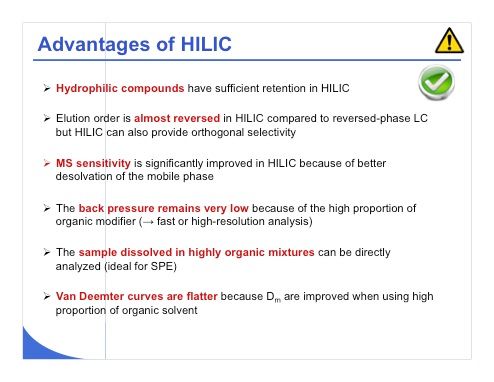
Slide 4: There are of course number of advantages related to HILIC, as listed in slide 4. The first one is that HILIC will allow sufficient retention of the most hydrophilic compound that does not possess sufficient retention under reversed-phase LC condition. The elution order will be almost reversed compared to reversed-phase LC, but it can also provide orthogonal selectivity and we will discuss some examples later. The very important advantage is MS sensitivity - it can be drastically improved because of a better desolvation of the mobile phase, which contains a huge amount of acetonitrile. Another important feature is that the back pressure remains very low in the HILIC mode because of the high proportion of organic modifier, which enables faster or high-resolution analysis. Finally, another advantage is the possibility to directly analyze solid-phase extraction (SPE) extracts in HILIC, because at the end of the SPE process, a huge amount of organic modifiers are present that are not critical for HILIC experiments. Van Deemter curves are also flatter when using a high proportion of organic solvent.
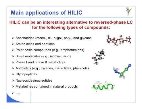
Slide 5: If we look at the main applications for HILIC, it is apparent that this strategy can indeed be a useful alternative to reversed-phase LC for several types of compounds (slide 5). For example, sugar derivatives and mono-, di-, and oligosaccharides can indeed be very well analyzed under HILIC conditions. Amino acids, peptides, polar basic compounds, and particularly metabolites are also very well analyzed under HILIC conditions with high MS sensitivity; we have also seen a number of applications with natural products and also with nucleosides or nucleotides. If you have trouble analyzing these kinds of polar compounds, HILIC may be a suitable strategy.
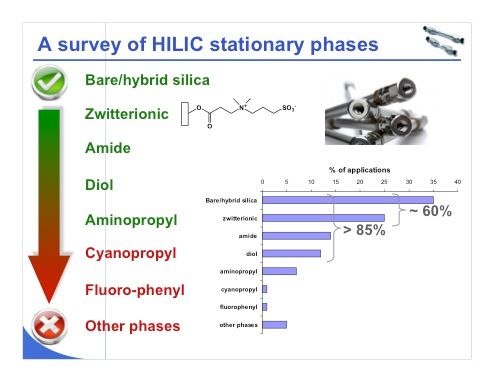
Slide 6: Slide 6 shows a survey of HILIC stationary phases in the literature. I have tried to give you an idea which stationary phase will be the most interesting for HILIC experiments, because a wide variety of stationary phases is available and only a few of them are really interesting for the first experiments at least. Generally, if we look at the bare–hybrid silica plus the zwitterionic phases, they will account for around 60% of HILIC applications, which means that bare silica and zwitterionic phases will be some of the most important stationary phases to have in your toolbox. Other important phases are the amide and diol phases. If we consider the first four phases listed in slide 6, it is clear that they have been used for more than 85% of HILIC applications. The other phases listed, including aminopropyl, cyanopropyl, and fluorophenyl, have been scarcely used. Some other phases, including urea and succinimide, can be employed, but they are not yet very widely applied.
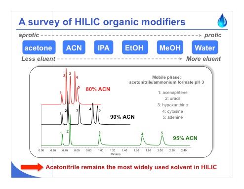
Slide 7: Slide 7 shows the same kind of survey, this time of HILIC organic modifiers. It is clear that acetonitrile remains the most widely used solvent in HILIC. When you perform your first HILIC experiments, you may be surprised to see that with increasing amounts of acetonitrile, retention increases because the water doesn’t have the same eluent strength in HILIC as in reversed-phase LC (see the chromatograms in slide 7). Finally, when you have a small proportion of water in the mobile phase, you will have a much longer analysis time. Acetonitrile is quite an aprotic solvent, but acetone is even more of an aprotic solvent. So acetone can also be employed in HILIC to obtain some nice separations. On the other hand, water is too protic and hydrophilic partitioning cannot occur. Methanol has the same problem. Generally, the more aprotic the solvent, the lower the eluent strength. On the other hand, the more protic the solvent, the higher the eluent strength.
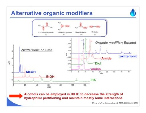
Slide 8: Slide 8 shows an example analysis that deals with hydrazine, and with these kinds of basic compounds, alcohol has been used as an organic modifier. When working with a zwitterionic column, which possesses both permanent positive and negative charge, we can see that it is even possible to retain hydrazine derivatives using isopropanol, ethanol, and even methanol. Why? When working with pure methanol, the strength of hydrophilic partitioning is decreased but there is some ion exchange with the hydrazines, which are positively charged. For this reason, we have again a competition between different mechanisms, and in this case, the hydrophilic partitioning will be almost negligible using pure methanol.
On the other hand, we can see on the right that when working with pure ethanol with a zwitterionic phase, the separation is improved because we have this permanent positive and negative charge, while when working with an amide, diol, or amino phase, the retention is much less and the separation is not acceptable. The amount of negative charge at the surface of the stationary phase is significantly lower compared to that observed on the zwitterionic one.
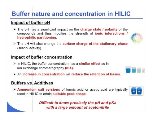
Slide 9: The nature of the buffer and its concentration are extremely important when working under HILIC conditions (slide 9). The pH has a significant impact on the charged state and also the polarity of the compound. Indeed, when you have a charged compound, its polarity will be significantly decreased; and if its polarity is decreased, you will have more retention in HILIC, which is exactly the reverse of what happens in reversed-phase LC. So we can easily modify the strength of the ionic interaction and the hydrophilic partitioning by simply modifying the pH under HILIC conditions. The pH will also change the surface charge of the stationary phase, and the silanol activity will be probably different when working at pH 3, 6, or even 9 in some cases. Changing the buffer concentration in HILIC will have much more impact than in reversed-phase LC, simply because we are doing much more ion exchange. In HILIC, the buffer concentration will have a similar impact to ion-exchange chromatography. When you increase the concentration of the buffer, you will reduce the retention of the basic compounds.
Finally, it is generally better to work with ammonium salt versions of formic acid or acetic acid instead of choosing simply 0.1% formic acid or acetic acid, because use of the ammonium salt versions will yield better peak shape. One of the main problems with buffer and pH is that it is very difficult to know the pH and pKa precisely when working with a large amount of acetonitrile. So clearly we don’t know really what the charge is at the surface of the stationary phase, the charge on the analyte, and the real pH at which we are working, which could be critical in some cases.
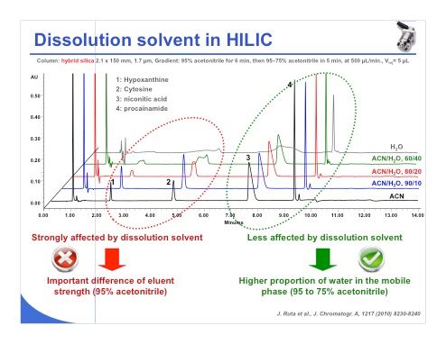
Slide 10: The choice of dissolution solvent is probably one of the most important problems that we encounter in HILIC. Indeed we can see in slide 10 that when dissolving the sample under pure acetonitrile, we have good peak shape for peaks 1–4. Adding some water to the sample eluent causes the peak shape to degrade, and when working with pure water as sample eluent, we can see that the peak shapes become completely unacceptable.
On the other hand, we can also observe that the effect of the dissolution solvent is strongly affected by the retention of the compound. Compounds that are poorly retained in HILIC will be more affected by the dissolution solvent, similar to the situation in reversed-phase LC. Compounds that are more strongly retained under early conditions are less affected by the dissolution solvent and accept a much higher proportion of water inside the mobile phase. In general, I would say that a mobile phase of 80% acetonitrile and 20% water is acceptable. If you reduce the percentage of acetonitrile, you may have some trouble with peak shape.
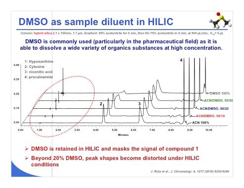
Slide 11: Dimethyl sulfoxide (DMSO) is also a very commonly used solvent, particularly in the pharmaceutical field, because it is able to dissolve a wide variety of organic substances even at high concentration. We have performed some experiments with DMSO (slide 11), and we have observed that DMSO was retained under HILIC conditions and masks the signal of compound number 1, which could be a problem. On the other hand, we have seen that when working with a mobile phase consisting of more than 20% DMSO, the peak shape began to be quite degraded. So a maximum of 20% DMSO should be used in the mobile phase to avoid distortion of the chromatographic peaks. In this case, we obtained some nice peak shapes.
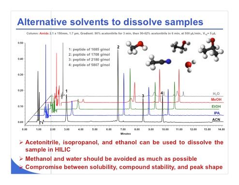
Slide 12: There are of course some alternative solvents that can be employed if the sample cannot be dissolved in pure acetonitrile or a large amount of acetonitrile. Surprisingly, even sugar at a quite high concentration can be dissolved in the 80:20 acetonitrile–water mixture, and it works quite nicely. If you have trouble with solubility, you can employ isopropanol, ethanol, methanol, or water, as reported here. Water clearly should be avoided as previously mentioned. In slide 12, with water the peak shape is very bad for a mixture of four peptides. Methanol is also not a good choice. We can see that the two first peaks have very poor peak shape. On the other hand, ethanol and isopropanol seem to be good candidates. Finally, it seems that the less protic the solvent, the better the peak shape. So finally when you want to dissolve your sample, you have to dissolve it in a solvent that will be quite aprotic or less protic than water or methanol.
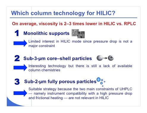
Slide 13: Which column technology should be employed for HILIC? We know that in reversed-phase LC, there has been a lot of work done regarding monolith, core–shell, and UHPLC technologies. In HILIC, the story is bit different (slide 13). Indeed, the typical viscosity in HILIC is 2–3 times lower compared to reversed-phase LC. For this reason, working with a monolithic support, for example, in HILIC is of limited interest simply because the pressure drop is not a constraint under HILIC conditions. The main advantage of a monolithic support is to significantly reduce the back pressure compared to a packed column. On the other hand, sub-3-µm core–shell particles are very attractive in HILIC in the same way they are attractive in reversed-phase LC; however, there is still a lack of available column chemistries, and at the moment we can only find two or three different column chemistries.
Using UHPLC or sub-2-µm fully porous particles is a very suitable strategy for HILIC simply because the two main constraints of UHPLC are that generally an instrument that is compatible with a very high pressure drop is needed and frictional heating can sometimes be a problem, and these two problems are no more relevant in HILIC because the back pressure will be 2–3 times lower compared to what we generally observe in reversed-phase LC.
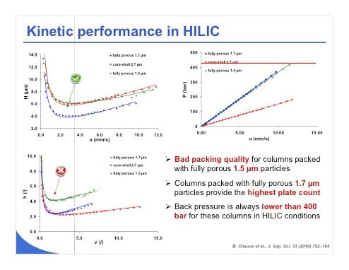
Slide 14: A recent study of ours deals with kinetic performance in HILIC. We tried to compare some fully porous sub-2-µm material with core–shell sub-3-µm material. Slide 14 shows that the performance of the fully porous 1.5-µm media is not as good as we might expect, because the green curve should be below the blue curve, which is not the case. However, the fully porous 1.7-µm and core–shell 2.7-µm particles work perfectly. This is also illustrated in the reduced plate-height value shown in the bottom left plot and we can see here that indeed the column with the fully porous 1.5-µm particles has a packing problem and was not reliable. On the other hand, the other columns provide a very high plate count and the back pressure as we can see in the plot at upper right remained always lower than 400 bar, no matter which technology we employed.
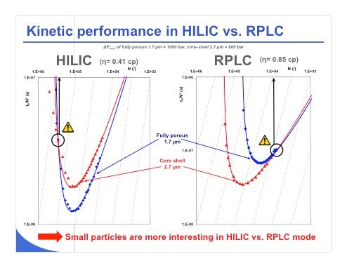
Slide 15: Now if we move one step forward and try to investigate the kinetic performance under HILIC and under reversed-phase LC conditions, we can see that the viscosity is indeed lower under HILIC conditions. Slide 15 shows kinetic plots for HILIC and for reversed-phase LC. This kind of plot can be difficult to read, but the curve must be as low as possible to demonstrate that one technique is better than the other one. In the reversed-phase LC plots on the right, we can see that for an efficiency of around 10,000 plates, we have almost equivalent performance between fully porous and core–shell material. However, for efficiency between 10,000 and 100,000 plates, we can see that the 2.7–µm core–shell material outperforms the fully porous 1.7-µm material.
On the other hand, for the plots on the left with HILIC material, the story is a bit different. We can say that the fully porous 1.7-µm curve is always below that of the 2.7-µm core–shell material, simply because we have lower viscosity and much less constraint in terms of pressure, which means that the fully porous 1.7-µm material will provide faster separations or higher resolution. So to conclude, small particles are much more interesting in HILIC versus reversed-phase LC and it makes no sense to work with a larger particle (for example, 5 µm) unless the correct stationary phase chemistry is unavailable with the sub-2-µm or core–shell particles. Indeed, working with a 5-µm particle in HILIC would be of limited interest because you will have a pressure in the columns between 10 and 20 bar, whereas the system is capable of working at pressures as high as 200–400 bar.
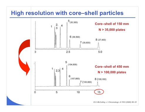
Slide 16: The chromatograms in slide 16 were obtained by Professor David McCalley and show that some very nice work in HILIC can be done with core–shell particles. He obtained a plate count higher than 35,000 plates with a 150-mm column length in HILIC. The compounds in this study were ionizable, and he extended the column length to more than 400 mm. The plate count became higher than 100,000 plates and the analysis time remained lower than 15 minutes, which is very impressive. So it is apparent that HILIC can be a good strategy to obtain very high plate counts compared to reversed-phase LC because we have much less constraint in terms of pressure.
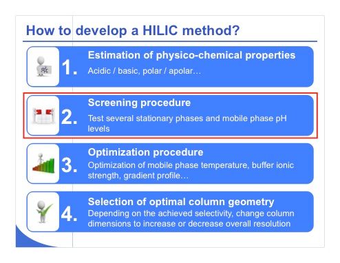
Slide 17: Now I would like to give you some insight about how to develop a HILIC method (slide 17). When we develop a reversed-phase LC method, we are trying to evaluate the physicochemical properties of the compound to determine whether it will be acceptable for reversed-phase LC or if it’s better suited for separation under HILIC conditions. Of course if you have a very polar compound, it will be much better suited for HILIC. If you have an ionizable compound, it could be analyzed successfully in both HILIC and reversed-phase LC. With an apolar compound, you will probably use reversed-phase LC. When you know that you have to work under HILIC conditions, the first thing to do would be to create a rapid screening procedure to test different columns and different mobile-phase pH values. It should require just a few hours to find a column and pH level that can be employed for the separation. If you find a suitable column and pH, then you can also optimize the separation and particularly the mobile-phase temperature, ionic strength, gradient profile, and so forth. Once you have obtained the optimal selectivity for the separation, you can try to customize the column geometry and increase or decrease the column length to increase or decrease the overall resolution to obtain a full separation of all the compounds.
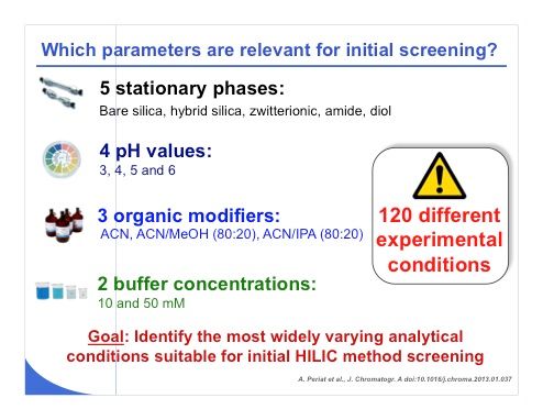
Slide 18: I would like to focus on the screening procedure for the moment, because not everything is clear in HILIC. Very recently in a study published in the Journal of Chromatography, A, we tried to evaluate which parameters were relevant for initial screening (slide 18). We examined five different stationary phases, namely bare silica, hybrid silica, zwitterionic, amide, and diol, which are representative of all the phases that are widely used under HILIC condition. All of them were packed with sub-2-µm particles. We tested four pH values and three organic modifiers. We did not test pure methanol or pure isopropanol, because we would have had too little retention for the compounds that we were investigating. We mixed acetonitrile with methanol and with isopropanol, or used pure acetonitrile and also tested some buffer concentrations at 10 and 50 mM because we know that ion exchange could be quite important. The goal of all these 120 experiments was to determine the most widely varying analytical conditions that are suitable for initial HILIC method screening.
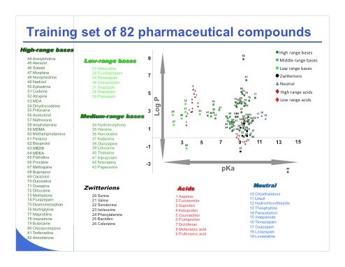
Slide 19: Slide 19 shows the training set of 82 pharmaceutical compounds employed in this study, including a few acid, neutral, and zwitterionic compounds. The set includes mostly basic drugs because it is representative of the pharmaceutical world.
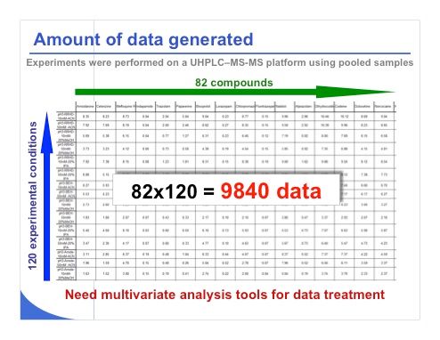
Slide 20: Slide 20 shows some of the data collected when we injected the 82 compounds within the 120 conditions that I previously described. To limit number of experiments, the 82 compounds were pooled in four different mixtures and the identification power of MS was considered to recognize each compound and measure the corresponding retention time obtained with the various stationary-phase and mobile-phase conditions. As shown in the slide, we collected nearly 10,000 data points. The next challenge is to find a way to treat this huge amount of information.
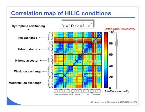
Slide 21: The first solution to treat this huge amount of data is to calculate the correlation coefficients between the different series of conditions. For this purpose, the S value originally introduced by Neue (see slide 21) is a good parameter because it provides a numerical value between 0 and 100 to assess similarity and differences between conditions. The values close to 0, which are coded in blue in this representation, correspond to a very similar selectivity between the two conditions on this map. A value of 100, which is coded in red on this graphical representation, demonstrates a lack of correlation between the set of conditions. This correlation map shows that the different stationary phase and pH combinations were compared to determine the most diverse conditions for this initial screening in HILIC. It appears that the amide and the bare silica phase were quite different in terms of selectivity. In addition, the zwitterionic phase at pH 3 and pH 4 behaved very differently from all the other column and pH combinations, which means that the zwitterionic phase is a bit special and working at pH 3 or 4 with the zwitterionic phase will probably provide a very different separation compared to any other conditions.
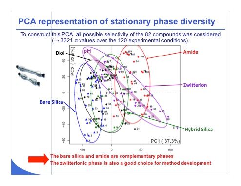
Slide 22: Another way to treat the data is to use a multivariate analysis tool. The plot in slide 22 looks very complex, but we will discuss only the most important points. This is a principal component analysis (PCA) representation. From the values shown on the x and y axes, 37% and 22%, we have around 60% of the total variance that was considered in this score-plot graph. Confidence ellipses at 80% were also added to this representation to improve the readability and allow a better visualization of group discrimination. The diol represented in black and the hybrid silica in green were very close — as you can see the ellipses are almost overlaid in term of selectivity, which means that these two columns are very similar. It wouldn’t make much sense to work with both of these phases for the set of compounds that we have selected.
On the other hand, the two most different phases were the base silica (blue) and the amide phase (red), which appear in two separated clusters. We can consider these two phases to be very different, and it could be of interest to investigate them during initial screening. Last, the zwitterionic phase (purple) behaved quite differently from the other phases. Its confidence ellipse is oriented in a different direction from the others. This phase may also be of interest for initial method development. In conclusion, among these five different phases, possibly only one should be discarded because it is not useful, probably the diol or hybrid silica phase. All the other ones look quite promising.
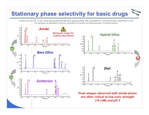
Slide 23: Slide 23 shows the separation of a mixture of seven compounds using the various stationary phases. The peak shape is quite bad for the codeine derivatives on the amide phase, which is surprising. In these five separations, the selectivity looks different for each phase except between the hybrid silica and the diol phases, where the separation was very close. So it is clear that one of these two columns is not useful for the investigated compounds.
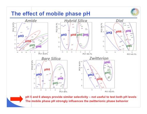
Slide 24: We can do the same work with pH and examine the resulting score plots (slide 24). Mobile-phase pH values of 5 and 6 provide similar selectivity for all of the stationary phases, so it is not useful to test both pH values with any of the stationary phases. Note that the mobile-phase pH strongly influences the zwitterionic phase. We can see that between pH 3 and 4 and pH 5 and 6, we have a very orthogonal selectivity, which means that working with a pH of 3 and 6 could be useful for all these different phases.
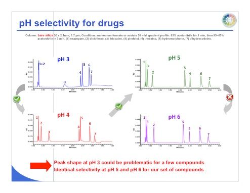
Slide 25: Slide 25 shows the separation of seven different compounds on bare silica at pH 3, 4, 5, and 6, and we can see again that between pH 5 and 6, we don’t have enough difference in terms of selectivity, while the selectivity changes more between pH 3 and 6.
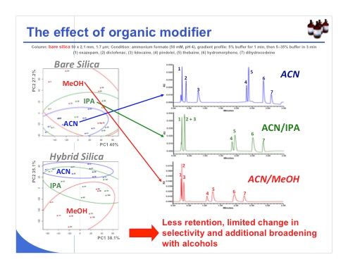
Slide 26: Last, regarding the effect of organic modifier, we can expect to have a lower change in selectivity, as shown in slide 26 for the bare silica phase, where the methanol, isopropanol, acetonitrile and confidence ellipses are quite overlaid. This overlap means that there is little change in selectivity. With hybrid silica, on the other hand, the selectivity changes when we add 20% methanol to acetonitrile. When working with organic modifiers such as isopropanol or methanol in the mobile phase, the retention decreases markedly and the selectivity changes very little, but they can cause significant additional band broadening. So we have to be careful, because these conditions are clearly not optimal.
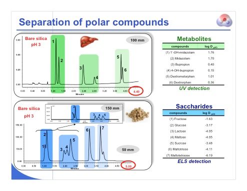
Slide 27: We will now look at few examples before discussing the use of MS detection with HILIC. Slide 27 shows the separation of some polar compounds. For the analysis shown in the top slide, there are three different drugs, and three metabolites. In this separation of a mixture of six compounds, the analysis time was quite short, and we were able to separate all the different drugs and metabolites without problem under HILIC conditions. The lower slide shows the separation of a mixture of different saccharides. We were able to separate the mono-, di-, tri-, and tetrasaccharides. The inset shows that we could use a longer column to separate the disaccharides (peaks 3–5) with higher resolution.
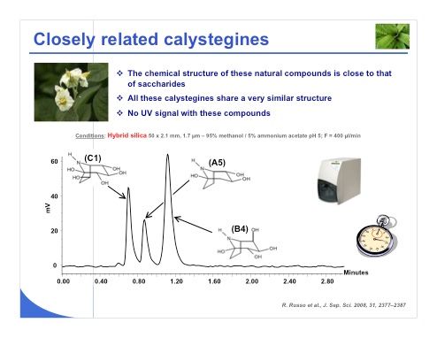
Slide 28:Another example that comes from the natural product side is the calystegines (slide 28). Their chemical structure is very close to that of saccharides. All of these calystegines have very similar structures, and they are non-UV active. So in this case we needed to use evaporative light scattering detection, which works well for HILIC. This method yielded a good separation with a very short analysis time for the three critical compounds.
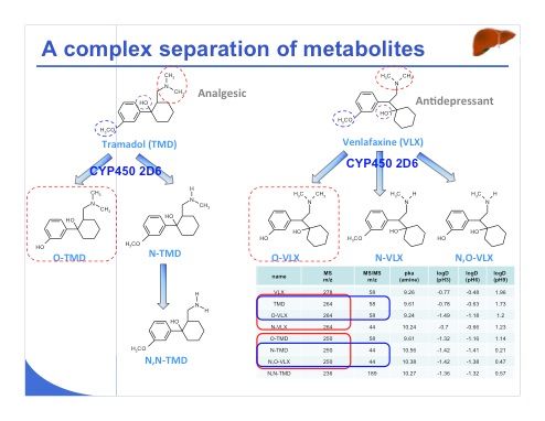
Slide 29:Another example of a bit more difficult analysis is the separation of two pharmaceutical compounds, namely venlafaxine and tramadol and their metabolites (slide 29), which were selected as model compounds. As we have seen elsewhere, false positive MS detection results were obtained for tramadol with patients who were also treated with venlafaxine because of the similar masses of the metabolites of venlafaxine and tramadol. This problem is illustrated in the table, which shows that some of the metabolites have the same mass-to-charge ratio or the same MS-MS transition; the structures of both drugs are very similar as are those of their metabolites. So for this reason, a suitable separation is necessary before detection with MS.
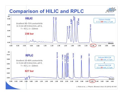
Slide 30:Another example of a bit more difficult analysis is the separation of two pharmaceutical compounds, namely venlafaxine and tramadol and their metabolites (slide 29), which were selected as model compounds. As we have seen elsewhere, false positive MS detection results were obtained for tramadol with patients who were also treated with venlafaxine because of the similar masses of the metabolites of venlafaxine and tramadol. This problem is illustrated in the table, which shows that some of the metabolites have the same mass-to-charge ratio or the same MS-MS transition; the structures of both drugs are very similar as are those of their metabolites. So for this reason, a suitable separation is necessary before detection with MS.
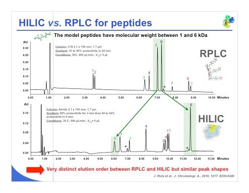
Slide 31: The last example is a peptide analysis (slide 31), where an impressive result was obtained with HILIC. We can see that in the reversed-phase separation, peaks 5 and 6 were resolved but the peaks were quite close. In the HILIC separation, peak 5 is the first peak eluted and peak 6 is last one eluted, which shows that not only is the elution order reversed, but we have a very different selectivity. It is also important to notice that peak 6 was insulin, so even with a small protein we can use HILIC and achieve an acceptable retention. It is the same with peaks 8 and 9 — the separation is limited in reversed-phase LC and is extremely good under HILIC conditions. So the selectivity is very different, we have a very distinct elution order between reversed-phase LC and HILIC, while the peak shape remains almost the same in both reversed-phase LC and HILIC separations.
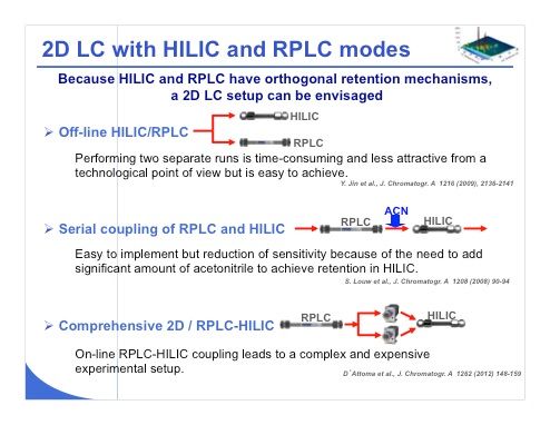
Slide 32: HILIC can also be employed in a 2D-LC setup because of the orthogonal retention mechanism in HILIC compared to reversed-phase LC (slide 32). There are three main ways to perform 2D-LC experiments with HILIC and reversed-phase LC. The first, probably simpler one, is to inject a sample in HILIC and also inject the same sample under reversed-phase LC conditions. With this approach, you have to perform two separate runs, which is of course less attractive from a technological point of view and also in terms of time because it will be much longer. Second, Pat Sandra’s group demonstrated that it was possible to couple reversed-phase LC and HILIC in series, provided that acetonitrile was added between reversed-phase LC and HILIC to obtain suitable peak shape. However, this approach could reduce sensitivity because the sample that is eluted from the reversed-phase LC column is being diluted before it enters the HILIC stationary phase. This is a serial column coupling. Last, the most evolved coupling, which is also complex and expensive, is to perform comprehensive 2D reversed-phase LC–HILIC. In this case, by using a switching valve, we can perform comprehensive LC by using reversed-phase LC in one dimension and HILIC in the other dimension. This approach has been demonstrated by the group of Sabine Heinisch at the University of Lyon in France; they showed that some nice separations can be obtained.
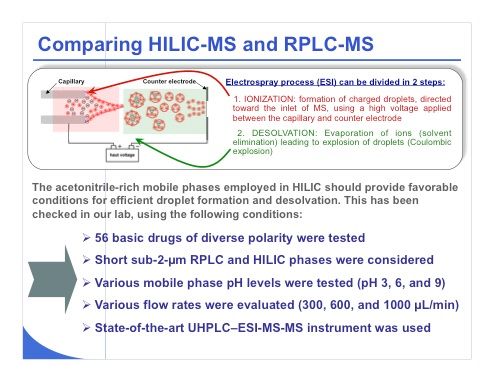
Slide 33:Now I move to the coupling of HILIC with MS and some comparisons that we have recently made in our laboratory with reversed-phase LC–MS. As a reminder, it is important to keep in mind that the electrospray process — the most widely used ionization strategy for LC–MS — includes two dissociated steps, the first one being ionization in which charged droplets are formed under high-voltage conditions. The second step is desolvation, and during this phase, the ions are evaporated from the mobile-phase constituents. The acetonitrile-rich mobile phases employed in HILIC should provide favorable conditions with electrospray ionization for efficient droplet formation and desolvation. Slide 33 shows the approach we used in our laboratory to test this theory: We analyzed 56 basic drugs of diverse polarity using exclusively short columns with sub-2-µm reversed-phase LC and HILIC phases. Various mobile-phase pH values were tested, namely pH 3, 6, and 9 (which was tested only under reversed-phase LC conditions). We tested flow rates of 300, 600, and 1000 µL/min, which are typical for use with a 2.1-mm i.d. column packed with sub-2-µm particles. All of these experiments were performed using a state-of-the-art UHPLC–triple-quadrupole MS system.
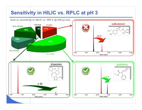
Slide 34: Slide 34 shows some of the results that we have obtained. Based on the 56 different compounds, we observed that approximately 11% of the compounds provided a lower sensitivity under HILIC conditions compared to reversed-phase LC, and conversely 89% of the compounds provided better sensitivity in HILIC versus reversed-phase LC, both at pH 3. Among the compounds that provided a better sensitivity, in some cases sensitivity improved by a factor of 1–5. For example, with pethidine we gained a factor of 2.9 between reversed-phase LC and HILIC. HILIC is shown in red in the chromatograms. On the other hand, the pie chart in the upper left part of the slide shows that some compounds provided gains in sensitivity of 5–10-fold, 10–30-fold (16% of the compounds), and greater than 30-fold under HILIC compared to reversed-phase LC. The example of triazolam shown in the slide is really an impressive case. A huge gain in sensitivity was obtained, with an improvement by a factor of 52 compared to reversed-phase LC.
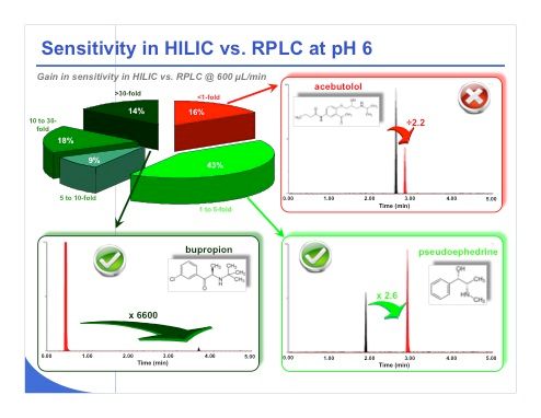
Slide 35:The same types of tests were performed at pH 6 and almost the same kind of performance was obtained (slide 35). Even more compounds provided very impressive gains compared to the previous results, with 14% of the compounds gaining in sensitivity by more than 30-fold in HILIC compared to reversed-phase LC. This improvement is amply illustrated with bupropion, which gained in sensitivity by a factor of 6600! For the other examples shown in the slide, pseudoephedrine or acebutolol, the peak shape looks very similar and the peak width is comparable. We don’t have more tailing in HILIC. We just have a huge gain in sensitivity under HILIC conditions.
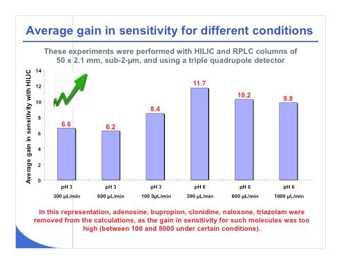
Slide 36: Slide 36 summarizes our findings here, and as you can see, when working at 300, 600, and 1000 µL/min at pH 3, we obtained an average gain in sensitivity for all these compounds of 6–8-fold. On the other hand, when working at pH 6, the gain in sensitivity was a factor of 10–12. So indeed we obtained a significant gain in sensitivity when working under HILIC conditions compared to reversed-phase LC. Some compounds — adenosine, bupropion, clonidine, naloxone, and triazolam — were removed from the calculations, because they showed extremely high gains in sensitivity, a factor of 100–8000 in some conditions. So if we were to include these compounds in the calculation, the result wouldn’t really represent an average gain in sensitivity. On average, we can expect a sensitivity gain of 7 at pH 3 and a gain of 10 at pH 6.
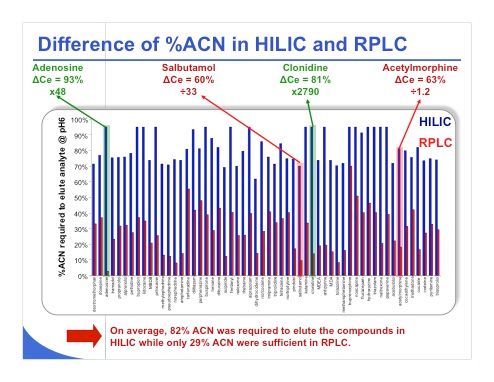
Slide 37:Slide 37 shows the difference of percentage of acetonitrile required to elute various compounds in HILIC and reversed-phase LC. The slide illustrates that on average, a mobile phase that consists of 82% acetonitrile is required to elute the compounds in HILIC. On the other hand, in reversed-phase LC only 29% acetonitrile is needed. So it’s true that there is a huge gap between reversed-phase LC and HILIC in terms of acetonitrile percentage. With adenosine, for example, a large difference in acetonitrile percentage (93%), is apparent between HILIC and reversed-phase LC compared to clonidine, where the difference is only 81%. However the sensitivity gain with clonidine will be much higher compared to that of adenosine. A similar relationship exists for salbutamol and acetylmorphine — they have the same difference of acetonitrile percentage between HILIC and reversed-phase LC, but the reduction of sensitivity for salbutamol is a factor of 33 whereas for acetylmorphine it is only 1.2. From this result, it is clear that acetonitrile probably plays the main role in sensitivity gain, but another factor could be important. It is possible that the ionization under HILIC conditions and reversed-phase LC could be very different because the pH values and the pKa values are strongly modified in presence of high acetonitrile content. So we need to explore this aspect in more detail but clearly, the percentage of acetonitrile is not the only factor that will impact the sensitivity in MS.
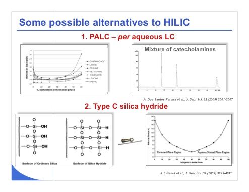
Slide 38: Of course, some possible alternatives to HILIC have been proposed for analyses that are problematic with reversed-phase LC. Pat Sandra’s group has shown a strategy that consists of using bare silica phases together with purely aqueous buffer as the mobile phase. As shown in the top half of slide 38, it is possible to avoid using the large amount of acetonitrile commonly required under HILIC conditions to adequately elute a mixture of amino acids or catecholamines. This strategy probably would result in a very low sensitivity in MS, because in this case the ions that must be desolvated are mostly associated with water — there is absolutely no acetonitrile or methanol. A second alternative, shown in the bottom half of slide 38, has been largely promoted by Joe Pesek and consists of using type C silica hydride in place of classical silica. It is indeed possible to have a reversed-phase LC-type retention mechanism when working at low percentage of organic modifier. This is illustrated on the bottom right of the slide. It is also possible to have a HILIC-type mechanism when working at high percentage of organic modifier with exactly the same stationary phase. Despite obvious advantages of this strategy and the availability of this phase over the past 5 years, these phases are not yet widely accepted in the industry. This will probably change in the future.
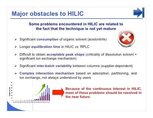
Slide 39: There are of course a few major obstacles to HILIC (slide 39). Some of the problems encountered in HILIC are related to the fact that the technique is not yet mature. First, HILIC requires a considerable consumption of organic solvent, namely acetonitrile, and this is clearly unavoidable. Second, the equilibration time has been reported to be longer in HILIC compared to reversed-phase LC. Factors of 2, 3, and even sometimes 4 have been reported, but no systematic studies have been conducted on this topic. Third, it is difficult to obtain acceptable peak shape in HILIC, particularly when first developing a method, and this is mainly related to the fact that the dissolution solvent is even more critical in HILIC than in reversed-phase LC. The peak shape problem is also related to the fact that a strong ion-exchange mechanism is present that broaden peaks. There is also a significant interbatch variability between columns, but this problem is really provider dependent. If you use a popular brand of stationary phase, you should not have to worry so much about interbatch variability. Last, the interaction mechanism is much more complex than in reversed-phase LC, because it is based on absorption, partitioning and ion exchange. This mechanism is not always well understood by users, and it is not so easy to work in HILIC when the basics of the technique are a mystery. However, because of the continuous interest in HILIC, I really think that most of these problems will be overcome in the future and there will be increasing interest in HILIC.
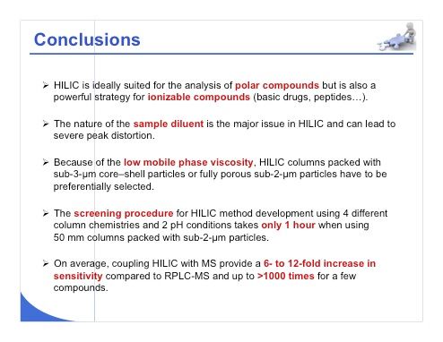
Slide 40: In conclusion, I would say that HILIC is ideally suited for the analysis of polar compounds, and that it is also a powerful strategy for ionizable compounds. Specifically, all basic drugs can be analyzed under HILIC conditions. We have tested more than 100 basic compounds, and peptides also can be analyzed successfully using this strategy. The nature of the sample diluent is probably the major issue in HILIC, and problems with the sample diluent can lead to peak distortion. So when you begin, do not dissolve your sample in pure water — if you do this you will be highly disappointed. Because of the low mobile-phase viscosity that exists under HILIC conditions, HILIC columns packed with sub-3-µm core–shell particles or fully porous sub-2-µm particles are valuable. These columns are indeed very interesting in reversed-phase LC, but they are even more interesting under HILIC conditions. So these phases must be preferentially selected. If column suppliers can provide more phase chemistries, even more interest will be generated in HILIC. The screening procedure that I discussed earlier with four different column chemistries and two pH conditions (recently published in the Journal of Chromatography) takes only 1 h when using 50-mm columns packed with sub-2-µm particles. With this approach, you can perform eight runs with equilibration in only 1 h using a switching valve to change between columns. Finally, for MS, there is a huge interest in using HILIC because it can provide a 6–12-fold increase in sensitivity compared to reversed-phase LC; and sensitivity gains of more than 1000 have been shown for a few compounds.
Slide 41:I would like to finish with some acknowledgments for my co-workers at University of Genève, particularly Prof. Veuthey, who is responsible for our research group, and Aurélie Periat, who is completing her PhD in HILIC and who participated considerably in the work discussed in this presentation.
< Back

.png&w=3840&q=75)

.png&w=3840&q=75)


.png&w=3840&q=75)


.png&w=3840&q=75)


