GC Troubleshooting in 20 Pictures (Part 1)
They say a picture paints a thousand words…This month I’ve taken inspiration from a recent webcast, presented at www.chromacademy.com, in which I presented real data from our work that represents some ‘classic’ GC problems.

They say a picture paints a thousand words…
This month I’ve taken inspiration from a recent webcast, presented at www.chromacademy.com, in which I presented real data from our work that represents some ‘classic’ GC problems.
The ability to recognise baseline and separation problems and identify their causes from the everyday pictures we see on our data systems, is a fundamental skill that every chromatographer should learn.
The first 10 of these is presented below, with a brief explanation of the potential cause and suggested fixes. You can use these to recognise similar problems in your own work – and build your ‘I’ve seen that before…….’ experience!
A simple test mix was used to reconstruct several of these problems and the test mix components and basic GC conditions were:

Column: DB5 30 m x 0.25 mm x 0.25 μm
Temp.: 70 °C, 20 °C/min to 250 °C
Carrier: He at 1.0 mL/min. (constant flow mode)
Inlet: Split (100:1) @ 250°C
Inj: 1mL
Detector: FID, 280 °C / H2, 45 mL/min. / Air, 450 mL/min. / He, 40 mL/min.
As you can see the test mix contains a good selection of neutral, acidic and basic compounds with a wide boiling range. The sample solvent is DCM.
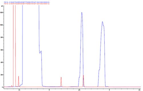
Chromatogram 1 shows peak overloading due to a sticking split vent valve or blocked split line. One can differentiate between mass overload and concentration overload by looking at the width of the solvent peak. Note the shoulders on the leading edge of the analyte peaks which often accompany volume overload and are caused by imperfections in the column cut at the inlet end.
One should regularly check that the split vent trap in the split line is not blocked and it’s a good idea to test the gas flows using an electronic flow meter periodically to see that they match. A sticking split vent valve is more difficult to diagnose but modern LC systems often provide an ‘on board’ test or a selection via the instrument panel to toggle the split valve between the open and closed state.
If mass overload is suspected check that the appropriate amount of analyte is being injected onto the column (typically between 20 and 500ng depending upon column i.d. and stationary phase film thickness)
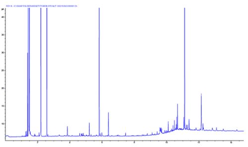
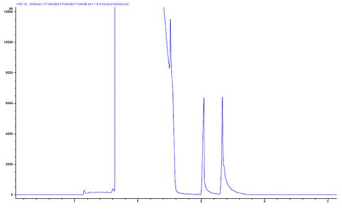
Chromatogram 2 shows ‘baseline spikes’. This spiking can often be caused by electronic interference – however these spikes show no gaussian shape when one zooms in. Here the spikes resemble highly efficient GC peaks, with variable peak height and no discernible retention time pattern.
This problem is caused by the GC column being installed too high in the FD detector and protruding into the flame. This causes the polyimide column coating to ‘bake’ which causes it to chip and the evolution of these small flakes into the flame causes the spiking behaviour.
Solve by lowering the column in the detector, following manufacturer’s installation advice.
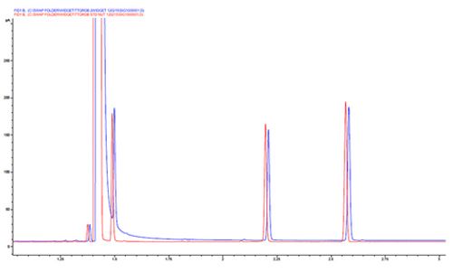
Chromatogram 3 shows a tailing solvent peak, which leads to issues with reproducible integration of the early eluting peak.
This issue can be caused by an improperly optimised splitless time, which causes slow evolution of the solvent vapours into the column. The splitless time should be reduced until the peak areas begin to reduce – then add 5 seconds back onto the splitless time. If the splitless time is too short, not all analyte will enter the column and sensitivity may be compromised.
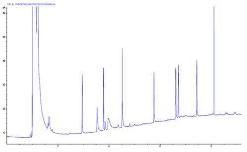
Chromtogram 4 shows that certain analyte peaks tail and one analyte is broad and tailing.
On further investigation, we see that the analytes which are tailing are the polar, acidic and basic analytes, and the tailing behaviour is caused by unwanted secondary interactions between the polar analyte functional groups and silanol groups on the column end, column inlet, quartz glass liner or glass wool liner packing material.
One should suspect that secondary chemical effects are in play when only certain peaks within the chromatogram show tailing behaviour.
These issues can be solved by improving column cutting technique (and examine cut using a magnifier), trimming 20cm from the end of the column, using a properly deactivated liner or fully deactivated glass wool respectively. Highly inert liner packing materials are also available.
Chromatogram 5 shows a broad solvent peak with badly tailing analyte peaks – all analyte peaks tail.
Here we should suspect that the column has been improperly installed into the inlet. Almost always, this results from the column being installed in the inlet. This interferes with the splitting process and leads to a slower than ideal introduction of analyte into the column inlet.
Lower the column within the inlet and follow manufacturers installation instructions.
Close inspection of the peaks in this example reveal a shoulder on the peak trailing edge, revealing that the column has also been poorly cut.
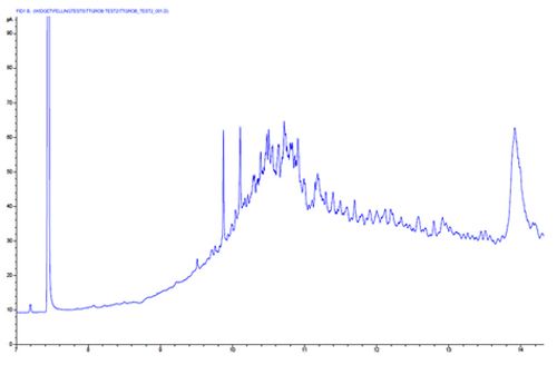
Chromatogram 6 shows high frequency, late eluting noise peaks which show a reasonably regular retention time pattern, with a gradual rise in the baseline position.
This type of baseline can be caused by the production of homologous species which elute into the detector. Typically the baseline rise might be caused by column stationary phase bleed – however this isn’t typically accompanied by the evolution of discrete peaks on the baseline.
In this case the ‘bleed’ products come from the inlet septum, and especially in splitless mode, the discrete bleed products become focussed at the column inlet during the low temperature portion of the analysis. Shards of septa within the inlet liner or a failure of the spetum purge gas flow can lead to such effects.
One should regularly check for septum debris within the inlet liner and check the septum purge flow periodically.
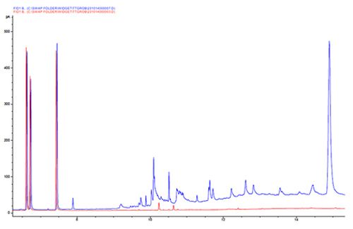
In contrast to the previous example, Chromatogram 7 shows the elution of highly adsorbed components from the GC column.
We show this example to highlight the difference between the regularly spaced peaks observed in septum bleed and the irregularly spaced peaks that are typical of the elution of strongly retained materials at high oven temperatures.
One should guard against the introduction of involatile materials through good sample preparation and include a high temperature portion at the end of each sample analysis to elute more highly retained materials after each sample injection.
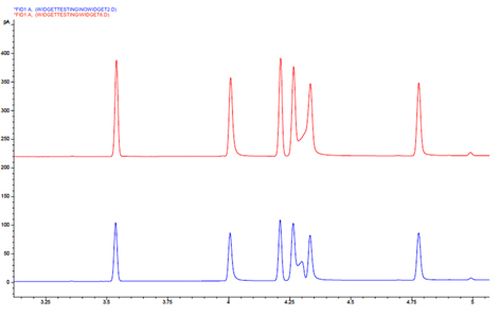
Chromatogram 8 shows the movement of certain peaks within the chromatogram, whilst the others remain at a fixed retention time.
This change in selectivity is more typical when dealing with mixtures of polar and non-polar analytes. When the degree of exposure to polar surface sites within the column changes, due to phase bleed or occlusion by highly adsorbed material, then the contribution to retention of polar analytes from secondary interactions with polar surface species, also changes.
These effects can be brought about by very subtle effects such as the reduction is film thickness at the column head as column bleed occurs or as silanol groups are occluded by the adsorbtion of involatile materials from the sample.
To investigate the underlying cause, one can remove 20–50cm from the column inlet and reinject the sample to see if the selectivity is restored. If this does not help then a new column may be required.
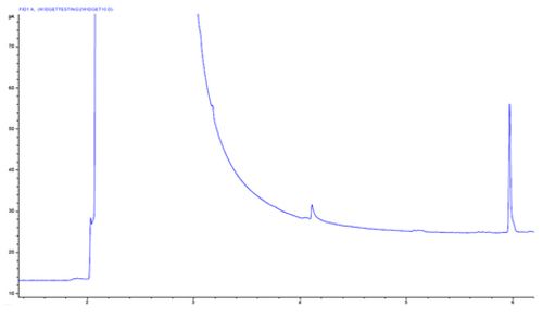
Chromatogram 9 shows a significant shift in baseline position across the solvent peak. This effect isn’t to be confused with baseline drift. It’s a shift, not a drift.
Any shift in baseline position is usually the result of a change in flow, especially when using a mass flow sensitive detector (such as an FID).
In this case the flow changes due to a slight leak which occurs during and after the injection caused by a split or cored septum which compromises the sealing of the inlet against the inlet pressure caused by the carrier gas flow.
One should check the condition of the septum prior to each campaign of analysis.
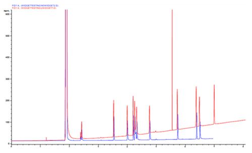
Chromatogram 10 shows a baseline drift over the course of the run, but crucially the retention times of the analytes do not change.
If the analyte retention times had increased across the run, then we might suspect that the carrier flow is slowing due to the carrier being operated in constant pressure mode (flow will decrease as the oven temperature increases).
As the retention times do not change we must suspect that the baseline position is changing for a different reason. One might consider column bleed if the stationary phase is a particularly thick film. For thinner films, the column bleed would tend to start much later in the run, where the oven temperature is much higher.
In this case, the baseline rise is brought about by an imbalance in the detector flow, here due to the make-up flow being set too low against the fuel and oxidiser flows. The change in response across the chromatogram is caused by the change in carrier gas pressure and the flame dynamics which would not be noticed if the make-up flow had been set correctly.
CHROMacademy Lite Membership is FREE and it only takes two minutes to register.
With a Lite Membership you are given access to:
- This month's webcast & tutorial
- Selected eLearning modules
- Featured CHROMacademy Content
- The CHROMacademy forum
Test drive CHROMacademy and Check out more great content available FREE to our Lite members »

Reversed Phase HPLC for the Analysis of Biomolecules
November 15th 2016Biopharmaceuticals offer great hope in treating medical conditions which are currently poorly served, at best, by traditional pharmaceuticals. It is estimated that there are over 400 biopharmaceuticals in clinical trials for in excess of 200 disease areas. The enhanced complexity and variability that comes from the size of biopharmaceuticals, allied with the intricacy of the production process, mean chromatography is employed to a much greater extent during production and release testing. The following article will introduce the fundamentals of biopharmaceutical analysis and cover the use of reversed phase HPLC in the analysis of biomolecules. A subsequent article will detail the application of HILIC, IEX, and SEC chromatography for the analysis if biomolecules.

.png&w=3840&q=75)

.png&w=3840&q=75)


.png&w=3840&q=75)


.png&w=3840&q=75)