GC Column Conditioning Stop Wasting Time and Money!
If you do Gas Chromatography, then you will have undoubtedly conditioned a capillary GC column ready for use after a period of storage or before first use.
If you ‘do’ Gas Chromatography, then you will have undoubtedly conditioned a capillary GC column ready for use after a period of storage or before first use. I see a lot of bad practice when columns are conditioned and so I thought that, even though this subject may have been covered many times, I’d try to produce a definitive guide with enough background information to explain why and how capillary GC columns should be conditioned.
Why do GC columns bleed and what is the bleed?
The stationary phase used in capillary columns will be a cured and chemically immobilized liquid polymeric material based on either a polysiloxane or a polyol.
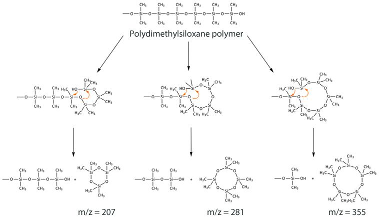
In the case of the polysiloxane based phase, the presence of oxygen catalyzes the cleavage of backbone siloxane units via a ‘back biting’ reaction as shown in Figure 1. Whilst this reaction is catalyzed at higher temperature, it also occurs at room temperature.

Figure 1: Reaction scheme for formation of cyclic polysiloxane bleed products from a dimethyl polysiloxane immobilised GC stationary phase.
The cyclic siloxanes formed are volatile, and elute from the column as bleed, which manifests itself as a rising baseline – and never as discrete peaks on the baseline.
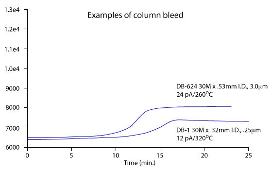
A classic stationary phase profile with increasing temperature is shown in Figure 2.

Figure 2: Typical capillary GC stationary phase bleed profile for two different polysiloxane based stationary phases (Figure reproduced with permission, Agilent Technologies, Santa Clara, CA, USA).
Column bleed is a continuous process. As analytical chemists it's our responsibility to ensure the bleed is at the lowest level possible and as constant as possible (i.e. no rising baselines with increased temperature).
On standing, the stationary phase will become oxidized and will bleed. Obviously one way to protect columns in storgae is to cap them – column caps are recommended as opposed to septa! One should also note that the reaction in Figure 1 is also catalyzed by UV light – which is why it’s a good idea to keep your capillary GC columns boxed between outings.
On column installation, it’s important to get rid of the bleed products formed during storage to ensure the lowest levels of baseline noise and baseline displacement during temperature programming. This is typically achieved using column conditioning, where the column temperature is eleveated slightly above the required upper working temperature and left there for a period of time to drive off the volatile bleed products.
Anyone over 40 who has done any HPLC analysis will propbably remember the practice of helium sparging to remove dissolved gasses in HPLC module phases – a practice a passing helium through a fritted sparger under pressure. The helium is excellent at solubilizing other gases (into itself) but is relatively insoluble in liquids – so effectively the helium sequesters the dissolved gases and then carries them out of the eluent solution.
Well – anyone using helium as a capillary GC carrier gas can also harness this power to remove dissolved gases (specifically oxygen) from their stationary phase, as well as physically removing the air from within the column itself. However, this must be done at room temperature in order to optimize the conditioning and not ‘waste’ phase by artificially creating column bleed. In essence, the very worst way to condition a capillary GC column is to install it, increase the oven temperature to the upper temperature limit (the gradient thermal maximum), and then leave it there for several hours……… You will simply be wasting time and money by conditioning columns in this fashion.
The required time and conditions actually depend upon the polarity of the stationary phase (more polar phases bleed more), the column length, internal diameter and thickness of the stationary phase film (longer columns with thicker films and larger internal diameters mean more stationary phase to bleed) and the required upper operating temperature (i.e. the top temperature in the analytical method to be used). These effects are also illustrated in Figure 2, where a more polar (DB-624), megabore, thick film column bleed profile is compared to that obtained with a non-polar column with smaller dimensions. The differences in bleed profile are clear and the factors outlined above are also critical in determining the upper working temperature of any GC column.
1. Connect the column to the GC inlet using good practice (clean cut, no finger marks, no shards of septum or ferrule stuck into the column inlet, column properly positioned in the inlet) – the inlet should be set the temperature specified in the analytical method, the oven at ambient temperature and the carrier gas should be flowing at the conditions stipulated in Table 1 below
2. Connect the column to the detector unless you do not want bleed products to enter the detector (MS detection used, or in line with you local policies and procedures)
3. Under these conditions allow at least column volumes of helium to pass through the column in order to remove air from the column as well as sparging any dissolved oxygen from within the stationary phase
1 column volume = L(mm) x(id/2)2 x π
For a 30 m x 0.25 mm column;
Column volume = 30,000 x (0.25/2)2 x π
Column volume = 1.472 mL
Therefore 6 column volumes = 1.472 x 6 = 8.84 mL
or 8.84 min at a carrier flow of 1.0 mL/min.
4. Once this step is completed, ramp the oven temperature (ensure the carrier gas is still flowing through the column) at 20 °C to 20 °C above the upper temperature required by the analytical method
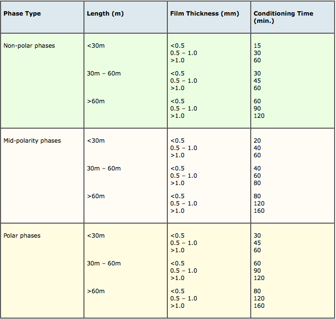
The length of time at the conditioning temperature and carrier gas flow rate at which this temperature should be maintained depends upon column phase and dimension and approximate recommendations are shown in the tables below;

Table 1: Required carrier flow rates for conditioning capillary columns of different dimension

Table 2: Recommended conditioning times for various capillary GC column types
5. Once conditioned, the column should be returned to the initial temperature required for the analysis and a visual assessment of baseline noise and drift made in order to confirm that the column is ready for use. System suitability standards may also be employed at this stage to make a quantitive assessment of fitness for purpose via Limit of Detection and Signal to Noise measurements.
As a brief aside – note that baseline rise can also be caused by running in constant carrier gas pressure mode with mass-flow sensitive detectors (such as FID) and one should aso consider this fact as a contributor to baseline displacement alongside the column bleed.
Finally, it is always good policy to record the bleed profile for a column when new (ref Figure 2), so that the level of bleed can be referenced at a later date in order to assess the degradation of the stationary phase over time and perhaps a performance limit established for column replacement. Just run the method without making an injection or inject a small amount of sample solvent.
If using mass spectral detectors, the presence of ions at 207 and 281 m/z indicate column bleed. These will almost always be there – it’s whether they are causing you problems either spectrally or in terms of reproducibility of integration that really matters!
For more information, contact either Bev (bev@crawfordscientific.com) or Colin (colin@crawfordscientific.com). For more tutorials on LC, GC, or MS, or to try a free LC or GC troubleshooting took, please visit www.chromacademy.com
The LCGC Blog: Historical (Analytical) Chemistry Landmarks
November 1st 2024The American Chemical Society’s National Historic Chemical Landmarks program highlights sites and people that are important to the field of chemistry. How are analytical chemistry and separation science recognized within this program?
